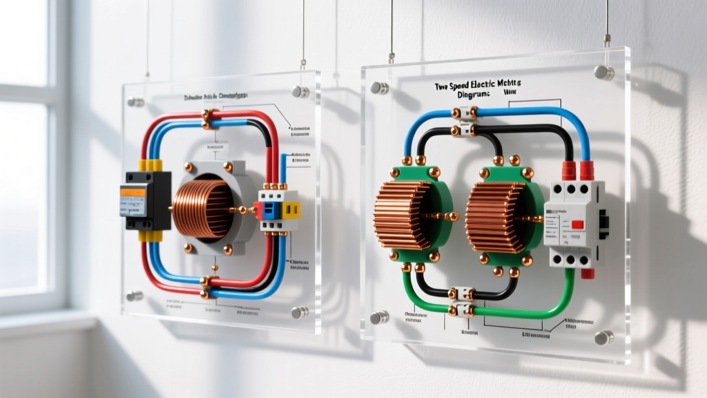

Understanding Two Speed Electric Motor Wiring Diagrams in 2026
While Variable Frequency Drives (VFDs) dominate modern industrial speed control, two speed electric motor wiring diagrams remain critical for fail-safe applications, high-EMI environments, and heavy-duty systems like marine pumps, smoke extraction fans, and dual-speed conveyors. Unlike VFDs, which can fail due to power surges or harmonic distortion, contactor-based two-speed motors offer bulletproof mechanical reliability. However, misinterpreting the wiring schematics for these motors is one of the most common causes of catastrophic stator burnouts in the field.
In this comprehensive tutorial, we decode the two primary architectures you will encounter in two speed electric motor wiring diagrams: the Dahlander (pole-changing) configuration and the Separate (dual) Winding configuration. We will cover terminal designations, control circuit interlocking, transition timing, and the critical overload sizing math that separates amateur wiring from professional, code-compliant installations.
Dahlander vs. Separate Winding: The Core Differences
Before touching a single wire, you must identify which type of motor you are wiring. The nameplate and terminal box layout will give you immediate clues. According to the NEMA MG-1 Standards for Motors and Generators, multi-speed motors are classified by their internal winding topology.
| Feature | Dahlander (Pole-Changing) | Separate Winding (Dual Winding) |
|---|---|---|
| Internal Windings | Single continuous winding with center taps | Two completely independent windings in one stator |
| Standard Terminals | 6 leads (1U, 1V, 1W, 2U, 2V, 2W) | 9 or 12 leads (e.g., 1-9 or T1-T12) |
| Speed Ratio | Strictly 1:2 (e.g., 1800 RPM / 3600 RPM) | Any ratio (e.g., 4-pole and 8-pole / 1800 / 900 RPM) |
| Torque Profile | Constant Torque (Delta/YY) or Variable (Y/YY) | Independent torque ratings for each speed |
| Typical Cost | Lower (less copper) | Higher (more copper, larger frame size) |
Decoding Dahlander (Pole-Changing) Wiring Diagrams
The Dahlander connection is an elegant method of changing the number of magnetic poles in the stator by reversing the current direction in specific coil groups. When reading two speed electric motor wiring diagrams for Dahlander motors, you will typically see six main terminals: 1U, 1V, 1W and 2U, 2V, 2W.
Low Speed Operation (Delta Connection)
For low speed (higher pole count), the motor is wired in a standard Delta configuration. Power is applied to 1U, 1V, and 1W. The 2U, 2V, and 2W terminals are left completely open and isolated. In this state, the current flows through the entire winding, creating a 4-pole (or 8-pole) magnetic field, resulting in half the synchronous speed.
High Speed Operation (Double Star / YY Connection)
For high speed (lower pole count), the winding topology shifts to a Double Star (YY). Power is applied to 2U, 2V, and 2W. Crucially, 1U, 1V, and 1W must be shorted together using a dedicated contactor to form the neutral star point. This reverses the current in half of the coil groups, effectively halving the pole count and doubling the RPM.
CRITICAL WARNING: Never apply power to both the 1-series and 2-series terminals simultaneously. Doing so will create a dead phase-to-phase short circuit, instantly destroying the contactors and potentially causing an arc flash. Mechanical and electrical interlocks are non-negotiable.
Wiring Separate Winding (Dual Winding) Motors
Separate winding motors are essentially two distinct motors housed in a single frame. The wiring diagrams for these motors are generally simpler to conceptualize because the windings do not interact electrically. You will typically find 9 or 12 leads in the peckerhead (terminal box).
- Low Speed Winding: Usually connected to leads T1, T2, T3, T7, T8, T9 (configured in Wye or Delta based on voltage).
- High Speed Winding: Usually connected to leads T4, T5, T6, T10, T11, T12.
When wiring the high-speed circuit, the low-speed winding must be left completely open. However, because the unused winding sits inside a rotating magnetic field, it can generate a dangerous induced voltage (back-EMF). Modern OSHA electrical safety guidelines and NEC standards require that the unused winding be safely isolated, and in some high-voltage applications, shorted through a discharge resistor to prevent voltage buildup that could degrade the winding insulation over time.
Control Circuit Design: Contactor Interlocking & Transition Timers
The power diagram is only half the battle; the control circuit is where the magic (and the safety) happens. When transitioning from low to high speed, or vice versa, the motor acts as a generator. If the high-speed contactor closes before the low-speed magnetic field has fully collapsed, the resulting back-EMF will clash with the incoming line voltage, causing massive current spikes.
The Transition Timer Rule
Professional two speed electric motor wiring diagrams always include an off-delay transition timer.
- Step 1: Stop command initiates. The active run contactor opens.
- Step 2: The transition timer (typically set between 0.5 to 1.5 seconds, depending on the motor's inertia and frame size) begins counting down.
- Step 3: During this dead time, the motor's residual magnetism decays.
- Step 4: The timer expires, allowing the new speed contactor to close safely.
In 2026, advanced motor protection relays like the Siemens SIMOCODE pro or Schneider Electric TeSys Giga series feature built-in transition logic and zero-crossing detection, eliminating the need for external analog timers and providing precise, software-controlled interlocking.
Overload Relay Sizing: The Most Common Sizing Mistake
The number one reason two-speed motors fail prematurely in the field is incorrect overload sizing. A motor's Full Load Amps (FLA) changes drastically between speeds. For example, a 10HP WEG Dahlander motor might draw 14.5A at 1800 RPM (Low Speed) and 26.2A at 3600 RPM (High Speed).
If you size a single thermal overload relay for the high-speed FLA (26.2A) and place it on the main line before the speed contactors, the low-speed winding will be completely unprotected. A 20A fault on the low speed will not trip the 26.2A overload, leading to a thermal burnout of the stator windings.
The Correct Sizing Architecture
To comply with NEC Article 430, you must use two separate overload relays (or a multi-setting electronic relay).
- Overload 1 (Low Speed): Placed in series with the low-speed contactor, dialed exactly to the low-speed nameplate FLA.
- Overload 2 (High Speed): Placed in series with the high-speed contactor, dialed exactly to the high-speed nameplate FLA.
Troubleshooting Edge Cases & Failure Modes
Even with perfect diagrams, field conditions introduce variables. When troubleshooting, reference the Fluke motor troubleshooting protocols for systematic isolation. Here are the most common edge cases specific to two-speed motors:
1. Motor Hums and Trips on High Speed (Dahlander)
The Cause: The shorting contactor (which bridges 1U, 1V, 1W for the YY connection) has failed or has pitted contacts. Without a solid neutral star point, the motor operates in a severely unbalanced single-phase state, drawing massive current and tripping the overload within seconds.
The Fix: Perform a voltage drop test across the shorting contactor poles under load. Replace the contactor if the drop exceeds 1-2V per phase.
2. Insulation Breakdown Between Windings (Separate Winding)
The Cause: Over years of thermal cycling, the insulation separating the low-speed and high-speed windings inside the stator slots degrades.
The Fix: Use a megohmmeter (Megger) at 500V or 1000V DC to test the insulation resistance between the T1-T3 set and the T4-T6 set. According to IEEE 43 standards, the resistance should be at least (Motor Voltage + 1000) / 1000 in Megohms. If it reads below 2 Megohms, the stator requires rewinding or replacement.
3. Contactor Welding Due to Back-EMF
The Cause: The transition timer is set too short (e.g., 0.1s), or the mechanical interlock is worn, allowing both contactors to briefly overlap during a direction/speed change. The resulting short circuit generates enough heat to weld the contactor contacts shut.
The Fix: Inspect contactors for mechanical play. Replace worn interlock blocks (e.g., Schneider LA9D series) and increase the off-delay timer to a minimum of 0.75 seconds.
Final Thoughts on Diagram Interpretation
Mastering two speed electric motor wiring diagrams requires looking beyond the power connections and understanding the electromagnetic physics happening inside the stator. Always verify the motor nameplate for the specific connection type (Delta/YY vs Y/YY), ensure your mechanical and electrical interlocks are redundant, and never compromise on dual overload protection. By adhering to these principles, you ensure your multi-speed installations remain robust, safe, and compliant with modern electrical standards.