
Mastering the 2003 Chevy Silverado Electrical Architecture
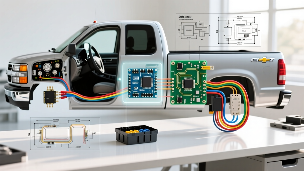
The 2003 model year represented a critical mid-cycle refresh for General Motors' GMT800 platform. Alongside the updated interior and revised front fascia, the 2003 Silverado introduced significant changes to its electrical topology, most notably an updated Body Control Module (BCM) and refined integration with the Delphi P59 Powertrain Control Module (PCM). Whether you are troubleshooting a parasitic draw, installing an aftermarket trailer brake controller, or diagnosing a no-start condition, securing an accurate wiring diagram for a 2003 Chevy Silverado is the mandatory first step.
Unlike modern CAN-bus (Controller Area Network) vehicles, the 2003 Silverado relies heavily on GM's Class 2 serial data line (SAE J1850 VPW). This single-wire multiplexing system operates at 10.4 kbps and daisy-chains the PCM, BCM, instrument cluster, and Supplemental Inflatable Restraint (SIR) modules. A short to ground on this single purple wire can disable the fuel pump relay, lock the steering column, and prevent the engine from cranking. Understanding these foundational circuits is what separates a parts-swapper from a true diagnostic technician.
Headlight and Daytime Running Light (DRL) Circuit Breakdown
One of the most frequently searched circuits in any 2003 Silverado wiring diagram is the headlight and DRL system. The GMT800 platform utilizes a complex Multifunction Switch (MFS) on the steering column, which acts as the primary logic gate for exterior lighting.
The Multifunction Switch Failure Mode
The OEM multifunction switch (ACDelco part # D6252E) is notorious for internal failures. The high current required for the high-beam headlights and the DRL relay coil routes directly through the switch's internal printed circuit board. Over time, the dielectric grease dries out, increasing resistance. This generates enough heat to melt the plastic housing and the solder joints on the PCB.
- Symptom: DRLs fail to illuminate, high beams only work when holding the flash-to-pass lever, or headlights remain on even with the key removed.
- Diagnostic Step: Pull the steering column shrouds and inspect the 14-pin connector at the base of the MFS. Look for melted plastic on the Tan/White (Left Turn) and Yellow (High Beam) wire cavities.
- Fix: Replace the switch with an updated ACDelco unit and apply dielectric grease to the connector pins. Do not bypass the DRL relay to force the lights on, as this alters the PWM (Pulse Width Modulation) voltage sent to the BCM, potentially triggering a U1000 Class 2 data code.
Critical Ground Points for Lighting
Before replacing the headlight switch, verify the primary lighting grounds. The 2003 Silverado routes the headlamp ground circuits to G100 (located on the left front fender, near the battery) and G102 (right front fender). Corrosion at G100 will cause the left headlight to dim and back-feed voltage through the high-beam indicator on the instrument cluster, a phenomenon known as a 'floating ground.'
Factory 7-Pin Trailer Wiring Harness Pinout
Towing is a primary use case for the Silverado 1500 and 2500HD. The 2003 model features an integrated 7-way RV blade connector located in the rear bumper. While the physical plug follows the industry-standard RV configuration, the wire colors inside the GM harness differ from standard aftermarket kits. When splicing into the rear junction block or troubleshooting a blown trailer fuse, refer to the table below.
| Pin Position | Function | RV Standard Plug Color | 2003 GM Harness Wire Color | Fuse Location (Underhood) |
|---|---|---|---|---|
| 1 (Top Left) | Backup / Reverse Lights | Red | Light Green | VEH BCK/UP 15A |
| 2 (Top Right) | 12V Auxiliary Power | Black | Red with Black Stripe | TRLR BATT 30A |
| 3 (Bottom Left) | Ground (Chassis) | White | Black (Heavy Gauge) | N/A |
| 4 (Center Left) | Left Turn / Stop | Yellow | Yellow | LT TRLR ST/TRN 10A |
| 5 (Center Right) | Right Turn / Stop | Green | Dark Green | RT TRLR ST/TRN 10A |
| 6 (Bottom Right) | Tail / Marker Lights | Brown | Brown | TRLR PARK 15A |
| 7 (Bottom Center) | Electric Trailer Brakes | Blue | Dark Blue | TRLR BRK 20A |
Pro-Tip for Brake Controllers: The 2003 Silverado comes pre-wired for a brake controller under the driver's side dash, taped to the main harness. The pigtail features a Red wire (12V ignition), a Dark Blue wire (output to trailer brakes), a Light Blue/White stripe wire (input from the stoplight switch), and a White wire (ground). You do not need to splice into the rear brake light wire; use the factory under-dash pigtail.
Delphi P59 PCM Connectors and Class 2 Data
For the 4.8L (LR4), 5.3L (LM7), and 6.0L (LQ4) Vortec V8 engines, the 2003 Silverado utilizes the Delphi P59 PCM. This unit features three massive 80-way connectors, color-coded Black (C1), Red (C2), and Gray (C3). When diagnosing sensor failures or injector misfires, referencing the exact pinout is vital to avoid piercing the wrong wire and shorting the 5-volt reference circuit.
Key PCM Pinouts (Connector C1 - Black)
- Pin 20 (Purple): Class 2 Serial Data. This is the communication gateway. If you cannot communicate with the PCM via the OBD2 port (DLC Pin 2), check this wire for a short to ground at the splice pack (SP205) located under the driver's side rear seat.
- Pin 21 (Pink): Ignition 1 Voltage. Supplies power to the PCM when the key is in the 'Run' position.
- Pin 18 (Orange): Battery Positive Voltage (Constant). Keeps the PCM memory alive. If this fuse (PCM BAT 15A) blows, the vehicle will crank but not start, and the anti-theft (Passlock) light will flash.
Injector and Coil Wiring (Connector C2 - Red)
The 2003 5.3L uses a sequential multi-port fuel injection system. The injectors are fed constant 12V from the fuel injector fuse in the underhood bussed electrical center. The PCM provides the ground path to fire the injector. The wire colors follow a specific GM pattern: Cylinder 1 is Dark Green/White, Cylinder 2 is Blue/White, Cylinder 3 is Brown/White, and so on. Always use a noid light or an oscilloscope to verify the PCM ground pulse before replacing injectors.
Common 2003 Silverado Electrical Failure Modes
As these trucks age well into the 2020s, specific wiring harness issues have become predictable. Recognizing these patterns saves hours of diagnostic time.
- Crankshaft Position Sensor (CKP) Harness Chafe: The wiring harness for the CKP sensor routes dangerously close to the exhaust manifold on the passenger side of the 5.3L. The heat shield degrades, melting the wire insulation. This causes an intermittent stalling issue when the engine is hot, often throwing a P0335 code. Inspect the last 6 inches of the CKP pigtail meticulously.
- Instrument Cluster Stepper Motor & PCB Cracks: While the stepper motors (X27.168) that control the gauges are mechanical failures, the underlying cause is often micro-cracks in the cluster's PCB solder joints due to thermal expansion. Before replacing all six stepper motors, reflow the solder on the main 16-pin power connector on the back of the cluster.
- Passlock II Anti-Theft Lockouts: The 2003 Silverado uses the Passlock II system, which embeds a Hall-effect sensor in the ignition lock cylinder. The thin yellow and black wires running from the lock cylinder to the BCM break inside their insulation near the tilt-steering pivot point. If the security light stays on solid and the truck starts then immediately dies, measure the resistance across the Passlock data line; an open circuit confirms a broken wire inside the steering column.
Essential Diagnostic Tools for GMT800 Trucks
Relying solely on a cheap code reader will not suffice for deep electrical diagnostics on a 2003 Silverado. To properly trace wiring diagrams and test circuits, equip your bench with the following:
- Bi-Directional OBD2 Scanner: Tools like the Topdon Phoenix Lite or Autel MaxiCOM allow you to command the BCM to turn on specific relays (like the cooling fans or fuel pump) while monitoring the wiring diagram for voltage drops.
- Digital Storage Oscilloscope (DSO): Essential for viewing the Class 2 VPW data waveform and verifying the 5V square wave from the cam and crank sensors.
- Back-Pinning Probes: Never use 'T-pins' or wire-piercing probes on the delicate 80-way PCM connectors. Piercing the insulation allows moisture to wick into the copper strands, causing green corrosion that will destroy a $400 PCM within a year. Always use dedicated back-pin probes to test connector terminals.
Sourcing OEM Wiring Diagrams and Service Data
While aftermarket repair databases are useful, they often contain transposed wire colors or omitted ground locations. For professional-grade accuracy, technicians rely on factory documentation. Helm Incorporated is the official publisher of General Motors Service Manuals. Purchasing the 2003 Silverado FSM (Factory Service Manual) provides over 2,000 pages of exact, fold-out wiring schematics, connector end-views, and diagnostic flowcharts that no free internet forum can match.
Additionally, staying updated on technical service bulletins (TSBs) is crucial. The National Highway Traffic Safety Administration (NHTSA) database allows you to search for manufacturer-issued electrical recalls and TSBs specific to your VIN, often revealing factory-acknowledged wiring harness routing flaws and their official repair procedures.
Finally, adhering to diagnostic standards set by ASE (Automotive Service Excellence) ensures that your testing methodology—from voltage drop testing to parasitic draw isolation—meets industry benchmarks, protecting both the vehicle's sensitive modules and your own safety.
Final Thoughts
Navigating the wiring diagram for a 2003 Chevy Silverado requires an understanding of its unique Class 2 architecture and the physical vulnerabilities of a two-decade-old harness. By focusing on the primary grounds, respecting the delicate PCM connectors, and utilizing the correct factory pinouts, you can confidently diagnose and repair the GMT800 electrical system with professional precision.