
Understanding the Wiring Diagram for Doorbell Transformer Circuits
Upgrading to a modern smart video doorbell or replacing a burnt-out mechanical chime system requires a precise understanding of low-voltage electrical routing. At the heart of this system is the doorbell transformer, a Class 2 power supply that steps down standard 120V AC household current to a safe 16V–24V AC. While the concept is straightforward, misinterpreting the wiring diagram for doorbell transformer setups is the leading cause of chime failure, Wi-Fi disconnects, and blown internal thermal fuses.
In this comprehensive appliance wiring tutorial, we will dissect the primary and secondary wiring schematics, calculate Volt-Ampere (VA) requirements for 2026 smart home devices, and provide a step-by-step installation guide that adheres to National Electrical Code (NEC) standards.
⚠️ CRITICAL SAFETY WARNING: The primary side of a doorbell transformer connects directly to 120V AC line voltage. Always turn off the corresponding circuit breaker at the main panel and verify zero voltage using a non-contact voltage tester or a multimeter (such as the Fluke 117) before touching any primary terminals. The secondary side is low-voltage, but a short circuit can still cause wires to overheat and melt.
Primary vs. Secondary: The Core Wiring Diagram Breakdown
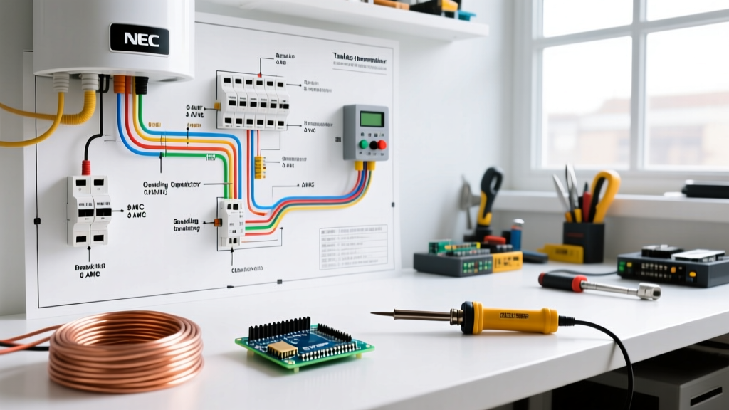
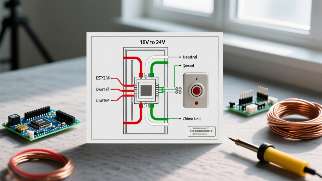
A standard doorbell transformer wiring diagram is split into two distinct circuits: the primary (high voltage) and the secondary (low voltage). Modern smart doorbells like the Ring Pro 2 or Google Nest Doorbell (wired) demand significantly more power than legacy mechanical buttons. Older transformers typically output 10VA, which is insufficient for continuous Wi-Fi streaming and night vision.
| Transformer Model | Output Voltage | VA Rating | Best Use Case | Avg. Price (2026) |
|---|---|---|---|---|
| Honeywell AT72P1 | 16V AC | 10VA | Legacy mechanical chimes only | $14.00 |
| Honeywell AT87N | 16V / 24V AC | 30VA | Smart video doorbells (Ring/Nest) | $24.50 |
| NuTone C905 | 16V / 24V AC | 30VA | Multi-chime homes / long wire runs | $28.00 |
When reviewing your wiring diagram for doorbell transformer configurations, note that the secondary terminals are non-polarized. Because the output is Alternating Current (AC), there is no positive or negative terminal. You can connect either secondary screw to the doorbell button and the other to the chime.
Step-by-Step Appliance Wiring Tutorial
Follow this exact sequence to ensure a safe, code-compliant installation. You will need 14 AWG or 12 AWG Romex for the primary connection (depending on your breaker size) and 18 AWG 2-conductor bell wire for the secondary side.
Phase 1: Primary Side (120V AC) Connections
- Prepare the Junction Box: The transformer must be mounted to a standard metal or PVC electrical junction box. Remove a 1/2-inch knockout from the box.
- Mount the Transformer: Feed the primary wire whip through the knockout and secure the transformer using the provided locknut. According to the Consumer Product Safety Commission (CPSC), all line-voltage splices must remain enclosed within a rated junction box with a solid cover plate.
- Wire the Primary Whip:
- Black Wire (Hot): Connect to the 120V line (usually black or red) using a wire nut.
- White Wire (Neutral): Connect to the neutral bundle (white wires) in the box.
- Green Wire (Ground): Connect to the bare copper ground wire and pigtail it to the junction box grounding screw.
- Secure and Test: Tuck the wires neatly, attach the junction box cover, and restore power at the breaker. Use a multimeter to verify 120V AC across the black and white wires before proceeding.
Phase 2: Secondary Side (Low Voltage) Routing
The secondary side utilizes 18 AWG bell wire. If your wire run from the transformer to the chime, and then to the front door button, exceeds 50 feet, upgrade to 16 AWG wire to prevent voltage drop. A voltage drop below 16V will cause smart doorbells to endlessly reboot.
- Terminal 1: Run an 18 AWG wire from the first secondary screw terminal directly to the 'Trans' (Transformer) terminal on your mechanical chime.
- Terminal 2: Run a second 18 AWG wire from the second secondary screw terminal to the front door button.
- Chime to Button: Run a final wire from the 'Front' terminal on the chime to the second terminal on the front door button.
Smart Doorbell Integration: Power Kits and Chime Connectors
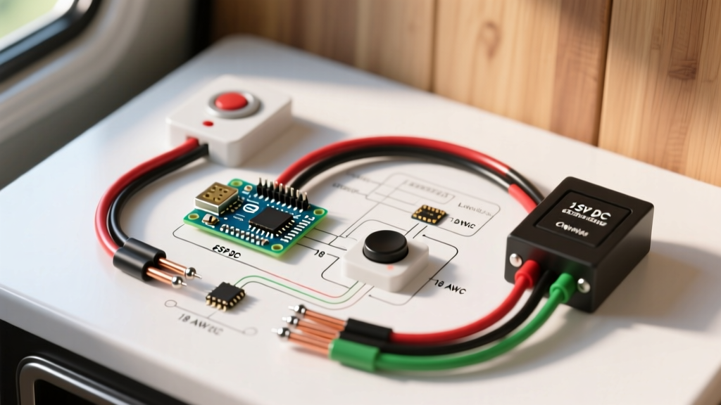
If you are wiring a smart doorbell, the standard wiring diagram must be modified. Smart doorbells draw a continuous micro-current to power their Wi-Fi radios, even when the button is not pressed. If this current passes through a mechanical chime coil, it will cause the chime to hum, overheat, and eventually burn out.
To prevent this, manufacturers include a Pro Power Kit (Ring) or a Chime Connector (Nest). This device is wired in parallel with the mechanical chime coil. It acts as a bypass, allowing the continuous micro-current to flow back to the transformer without energizing the chime's electromagnet. When the button is pressed, the kit redirects the full 16V-24V AC surge to strike the chime.
Expert Tip: If your home does not have a mechanical chime, you must install a 25-ohm, 50-watt wirewound resistor across the secondary terminals at the transformer to simulate the chime's resistance, or the smart doorbell will fail to boot.
Troubleshooting Common Transformer Failure Modes
Even with a perfect wiring diagram for doorbell transformer execution, environmental factors and component degradation can cause issues. Use this diagnostic matrix to identify the root cause.
| Symptom | Root Cause Analysis | Corrective Action |
|---|---|---|
| Chime hums continuously | Doorbell button is stuck in the 'closed' position, or wires are shorted behind the button. | Disconnect button wires. If humming stops, replace the button. Check for pinched 18 AWG wires in the door jamb. |
| Smart doorbell reboots randomly | Insufficient VA rating (e.g., using a 10VA transformer) or severe voltage drop over long wire runs. | Upgrade to a 30VA transformer (Honeywell AT87N). Measure voltage at the doorbell; it must be >16V AC. |
| Doorbell has zero power | Internal thermal cutoff fuse inside the transformer has tripped due to a previous short circuit. | Transformers are non-serviceable. Replace the unit. Ensure the secondary wires are not touching. |
| Breaker trips when button pressed | Primary side short circuit, or transformer internal winding failure (rare). | Inspect primary wire nuts for bare copper exposure. Replace transformer if primary is verified safe. |
NEC Code Compliance and Safety Standards
Doorbell circuits fall under NEC Article 725: Class 1, Class 2, and Class 3 Remote-Control, Signaling, and Power-Limited Circuits. As detailed in EC&M's analysis of NEC requirements, Class 2 circuits are inherently safe from fire initiation because the power source is limited in both voltage and current. However, the separation between Class 2 (low voltage) and Class 1 (line voltage) wiring is strictly enforced.
Never run 18 AWG bell wire inside the same conduit or junction box compartment as 120V AC Romex unless a physical, UL-listed barrier separates them. The transformer itself serves as this barrier. Furthermore, the transformer must be UL-listed and securely fastened; simply leaving it resting on a floor joist with exposed primary splices is a severe code violation and a fire hazard.
For further reading on safe DIY electrical practices and junction box fill calculations, refer to the comprehensive guides provided by The Family Handyman. By respecting the wiring diagram, calculating your VA loads accurately, and adhering to Class 2 separation rules, your doorbell system will provide reliable, safe service for decades.