
Mastering the Wiring Diagram for Pressure Switch Well Systems
The pressure switch is the central nervous system of any residential or agricultural well water setup. It monitors the hydrostatic pressure in your bladder tank and signals the submersible or jet pump to cycle on and off. However, because these devices bridge the gap between high-volume water plumbing and high-amperage electrical circuits, they present severe shock and fire hazards if installed improperly. As of the 2026 National Electrical Code (NEC) cycle, inspectors are heavily scrutinizing rural and private well installations for code compliance, specifically regarding grounding and motor disconnects.
This guide provides a comprehensive, safety-first wiring diagram for pressure switch well configurations, focusing on the industry-standard Square D Pumptrol (9013FSG2) and Flotec equivalents. We will bypass generic DIY fluff and dive directly into NEC Article 430 (Motors) and Article 250 (Grounding and Bonding) requirements to ensure your system is both operational and legally compliant.
Critical NEC Code Requirements for Well Pumps
Before stripping a single wire, you must understand the regulatory framework governing well pump circuits. The National Fire Protection Association (NFPA 70) outlines strict rules for motor circuits that differ from standard residential lighting or receptacle circuits.
1. Grounding the Metal Well Casing (NEC 250.112)
One of the most frequently failed inspection points in well pump wiring is the failure to ground the metal well casing. NEC Section 250.112(L) explicitly mandates that metal well casings must be bonded to the equipment grounding conductor (EGC). If a submersible pump's internal insulation fails and energizes the drop pipe, the metal casing will remain lethally charged unless properly bonded to the ground wire running back to the main service panel.
2. The Disconnecting Means (NEC 430.102)
You cannot simply wire a pressure switch directly to a breaker panel without a local disconnect. NEC 430.102 requires a disconnecting means to be located 'within sight' of the motor controller (the pressure switch). This is typically achieved by installing a 240V AC disconnect box (like a Square D D221NRB) or a dedicated double-pole breaker lockout mechanism within 50 feet and direct line-of-sight of the pressure switch.
3. GFCI and AFCI Nuances
While the NEC has aggressively expanded GFCI and AFCI requirements in recent cycles, hardwired 240V dedicated well pump circuits are generally exempt from standard GFCI breaker requirements to prevent nuisance tripping that would leave a property without water. However, if your pressure switch is plugged into a receptacle (which is itself a code violation for dedicated pumps in most jurisdictions), GFCI rules apply. Always verify local municipal amendments, as some regional health departments mandate specialized motor-rated ground-fault protection.
The Core Wiring Diagram: Line, Load, and Ground
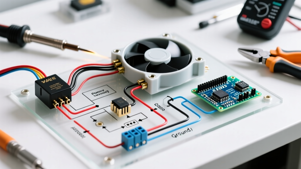
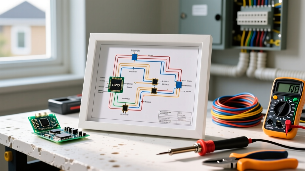
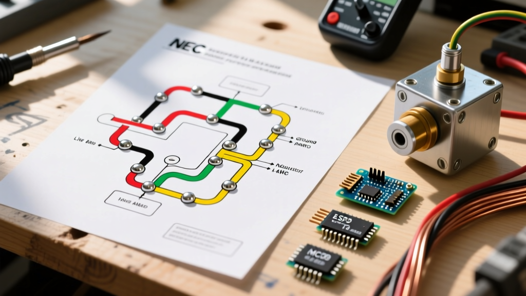
The standard 240V well pump pressure switch features four main terminal screws and a grounding lug. Understanding the distinction between 'Line' and 'Load' is critical for safe troubleshooting later.
- Line Terminals (L1 & L2): These receive the incoming 240V power from your breaker panel or local disconnect switch. They are 'always hot' when the breaker is on.
- Load Terminals (L1 & L2): These send the switched 240V power down the well to the submersible pump or out to the jet pump motor. They are only energized when the switch contacts are closed (calling for water).
- Grounding Lug (Green Screw): This must connect the incoming EGC from the panel to the outgoing EGC heading to the pump, as well as a bonding jumper to the metal plumbing and well casing.
Safety Warning: Never assume the 'Line' and 'Load' markings on aftermarket or generic pressure switches are accurate. Always verify the internal contact bridge mechanism. On the Square D 9013FSG2, the bottom terminals are typically Line, and the top are Load, but you must trace the physical contact arms to be 100% certain before energizing.
Wire Gauge and Breaker Sizing Matrix
Undersized wiring causes voltage drop, leading to premature pump motor burnout and melted pressure switch contacts. The following matrix assumes a standard 240V single-phase submersible pump setup. For runs exceeding 100 feet, voltage drop calculations dictate upsizing the wire, even if the ampacity table allows a smaller gauge.
| Pump HP | Voltage | Full Load Amps (FLA) | Min Wire (Under 100ft) | Min Wire (100ft - 250ft) | Breaker Size |
|---|---|---|---|---|---|
| 1/2 HP | 240V | 6.0 A | 14 AWG Copper | 12 AWG Copper | 15A (2-Pole) |
| 3/4 HP | 240V | 8.0 A | 12 AWG Copper | 10 AWG Copper | 20A (2-Pole) |
| 1.0 HP | 240V | 10.0 A | 12 AWG Copper | 10 AWG Copper | 20A (2-Pole) |
| 1.5 HP | 240V | 14.0 A | 10 AWG Copper | 8 AWG Copper | 30A (2-Pole) |
| 2.0 HP | 240V | 18.0 A | 10 AWG Copper | 6 AWG Copper | 30A (2-Pole) |
Note: Wire sizes listed are for THHN/THWN in conduit or direct-burial UF-B. Always refer to the specific motor manufacturer's nameplate for exact FLA and minimum circuit ampacity (MCA).
Step-by-Step Installation & Torque Specifications
According to OSHA Electrical Safety guidelines and standard electrical best practices, loose terminations are the leading cause of electrical fires in motor circuits. Follow this exact sequence for terminating your pressure switch.
- Lockout/Tagout (LOTO): Turn off the double-pole breaker at the main panel. Use a non-contact voltage tester and a calibrated digital multimeter (e.g., Fluke 117) to verify 0V across Line 1, Line 2, and Ground.
- Strip and Prepare: Strip exactly 1/2 inch of insulation from your 12 AWG or 10 AWG solid or stranded copper wires. Do not nick the copper conductor, which creates a weak point for future breakage under vibration.
- Terminate Line (Incoming Power): Connect the black and white (re-identified with black tape) wires from the panel to the bottom 'Line' terminals.
- Terminate Load (Outgoing to Pump): Connect the black and white wires heading to the wellhead to the top 'Load' terminals.
- Apply Precise Torque: This is where most DIYers fail. The terminal screws on a Square D Pumptrol FSG2 require 12 to 14 inch-pounds of torque. Use a calibrated torque screwdriver. Under-torquing causes arcing and melted plastic; over-torquing strips the brass threads.
- Bond the Ground: Connect the incoming bare copper ground and the outgoing bare copper ground to the green grounding lug. Additionally, run a 10 AWG or 8 AWG bare copper bonding jumper from this lug to the metal well casing and the metal plumbing tee body.
- Connect the Pressure Tube: Apply a small amount of food-grade silicone grease to the 1/4-inch brass barbed fitting. Slide the polyurethane or copper pressure tube over the barb and secure it with a stainless-steel hose clamp. Do not use Teflon tape on the barb, as shredded tape can enter the switch diaphragm and cause it to stick.
Common Failure Modes and Edge Cases
Even with a perfect wiring diagram, environmental and mechanical factors can compromise the system. Understanding these edge cases separates a novice from a master technician.
Edge Case 1: Rapid Cycling (Chattering)
If your pressure switch clicks on and off rapidly (every 3-5 seconds), do not assume the switch is broken. In 90% of cases, this is caused by a waterlogged bladder tank. If the tank's internal rubber bladder ruptures or loses its pre-charge air pressure, water becomes incompressible in the lines. The pump instantly hits 50 PSI, shutting the switch off, and the pressure drops to 30 PSI the moment a faucet opens, turning it back on. Fix: Check the Schrader valve on the tank with a tire gauge. It should read 2 PSI below the cut-in pressure (e.g., 28 PSI for a 30/50 switch) when the tank is completely drained of water.
Edge Case 2: Melted Thermoplastic Housing
If you open the switch cover and smell burnt ozone or see brown scorch marks around L1 or L2, you have experienced a high-resistance connection failure. This happens when 10 AWG stranded wire is not properly ferrule-crimped before insertion, or when torque specs are ignored. The arcing generates immense heat, eventually melting the switch housing and risking a ground fault. Fix: Replace the switch immediately. Do not attempt to salvage burnt contacts. Upgrade to a heavy-duty switch with larger contact surfaces if running a 2 HP pump.
Edge Case 3: Lightning and Surge Damage
Submersible pumps act as massive ground rods, making them highly susceptible to lightning strikes and grid surges. A surge can weld the internal contacts of the pressure switch shut, causing the pump to run continuously until it burns out or the pipe bursts. The EPA recommends installing a dedicated well pump surge arrestor (like the Intermatic IG1204RC3) at the breaker panel to protect the pressure switch and the pump's control box capacitors.
Final Inspection Checklist
Before restoring power, run through this final compliance checklist to ensure your installation meets the highest safety standards:
- [ ] All terminal screws torqued to 12-14 in-lbs.
- [ ] White wires used for 240V loads are permanently re-identified with black or red electrical tape at both ends.
- [ ] Metal well casing is bonded to the equipment grounding conductor.
- [ ] Local disconnect is installed within sight of the pressure switch.
- [ ] Pressure switch cover is fully seated and secured with the factory locknut to prevent dust and moisture ingress.
By adhering strictly to this wiring diagram and the underlying NEC safety principles, you ensure a reliable, long-lasting, and legally compliant well water system that protects both your property and your family from electrical hazards.