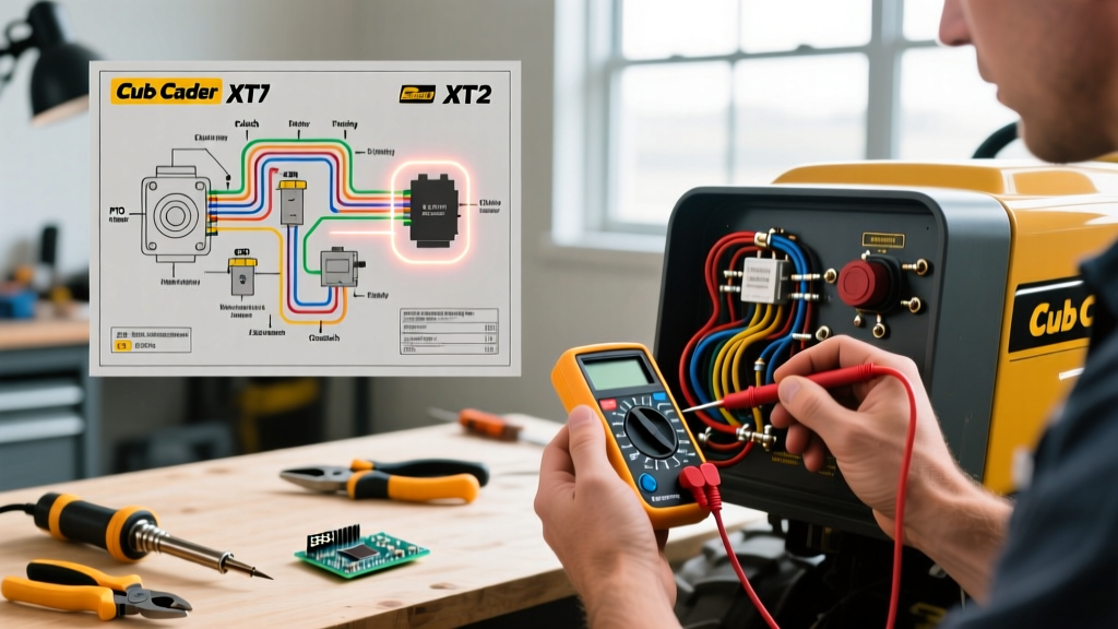

Introduction to the Cub Cadet XT1 & XT2 Electrical Architecture
When maintaining or repairing modern lawn tractors, understanding the specific electrical layout is non-negotiable. The wiring diagram for Cub Cadet XT1 and XT2 Enduro series tractors represents a significant evolution from older, purely mechanical MTD platforms. These models integrate a complex Safety Interlock Module (SIM), a Kohler 7000 Series engine harness, and a high-amperage Power Take-Off (PTO) clutch circuit. Whether you are diagnosing a no-crank condition, a PTO that refuses to engage, or a parasitic battery drain, relying on guesswork will lead to fried modules and wasted time.
In this comprehensive 2026 guide, we decode the factory wiring schematics for the XT1 (e.g., XT1 LT42, XT1 LT46) and XT2 (e.g., XT2 LX42, XT2 LX46) models. We will cover exact multimeter diagnostics, wire color coding standards, and common failure points specific to the Kohler-powered Enduro chassis.
Decoding the Wiring Diagram for Cub Cadet Tractors
Factory wiring diagrams can look like a bowl of spaghetti to the untrained eye. However, MTD (the parent company of Cub Cadet) adheres to a relatively consistent color-code matrix across its 2024-2026 production runs. When you pull the OEM schematic from the PartsTree Cub Cadet database or your operator's manual, look for these primary circuit identifiers:
- Red (R): Unswitched 12V DC battery positive. Routes directly from the battery to the starter solenoid and the main ignition switch 'B' terminal.
- Black (B): Chassis ground. Connects to the engine block, frame rails, and the negative battery terminal.
- Purple (P): PTO clutch engagement circuit. Carries 12V from the PTO dash switch (or SIM) to the electromagnetic clutch coil.
- Green (G) / Yellow (Y): Alternator/Stator AC output and DC rectified charging circuit. Routes from the Kohler engine stator to the voltage regulator/rectifier.
- White (W): Lighting and accessory circuits (headlights, hour meter illumination).
Critical Circuit Breakdowns
1. The Starter Solenoid and Ignition Circuit
The XT1 and XT2 utilize a 4-post or 3-post starter solenoid (depending on the exact year and whether it features a secondary ground interlock). When you turn the key to 'Start', the ignition switch sends 12V through the brake pedal safety switch and the PTO disengagement switch to the solenoid's 'S' (trigger) terminal. If the PTO is engaged or the brake is released, the circuit is broken at the switch level, preventing the starter from cranking.
Expert Tip: A common misdiagnosis is replacing the starter motor when the tractor clicks but won't crank. Before replacing the $140-$180 Kohler starter (Part #32 098 01-S), check the voltage drop across the solenoid's main posts while the key is held in the 'Start' position. A drop greater than 0.5V indicates welded or corroded internal solenoid contacts, not a bad starter.
2. The PTO (Power Take-Off) Clutch Circuit
The electric PTO clutch (typically an Ogura or Warner unit, such as the OG-533-3) is one of the highest-draw components on the tractor, pulling between 3.5 and 5.0 amps upon initial engagement. The wiring diagram shows this circuit protected by a 10A or 15A inline fuse or a dedicated circuit breaker located under the dash.
If your PTO fails to engage, the wiring diagram directs you to check three things: the PTO switch continuity, the inline fuse, and the clutch coil resistance. According to Kohler Engine service documentation, the electrical load of the PTO must be balanced against the stator's charging output; if the battery is weak, the PTO clutch may chatter or fail to pull in the armature.
3. The Safety Interlock Module (SIM)
Later XT2 models utilize a solid-state SIM rather than discrete mechanical switches wired in series. The SIM monitors the seat switch (operator presence), brake pedal, and PTO switch. If the operator leaves the seat while the PTO is engaged and the brake is not locked, the SIM cuts the ground path to the ignition coils, killing the engine instantly. Troubleshooting a SIM requires a wiring diagram to identify the specific input/output pins, as you cannot simply bypass a solid-state module with a jumper wire without risking a short circuit.
Multimeter Diagnostics: Real-World Values
When using a digital multimeter (DMM) to trace the wiring diagram for Cub Cadet models, you need exact baseline values. The following table provides the definitive diagnostic matrix for the XT1/XT2 electrical system.
| Component | Multimeter Setting | Expected Reading (Pass) | Failure Symptom | Corrective Action |
|---|---|---|---|---|
| Battery (Resting) | DC Volts | 12.6V - 12.8V | Slow crank, SIM resets | Load test; replace if < 12.4V |
| Stator AC Output | AC Volts | 28V - 35V AC @ 3000 RPM | Battery drains while mowing | Check stator wiring; replace stator |
| Voltage Regulator | DC Volts | 13.8V - 14.4V DC @ 3000 RPM | Overcharging / boiled battery | Verify ground; replace regulator |
| PTO Clutch Coil | Ohms (Ω) | 2.0Ω - 4.0Ω | Blown PTO fuse, no engagement | Replace clutch assembly |
| Seat Safety Switch | Continuity / Ohms | 0.5Ω (Depressed) / OL (Released) | Engine dies when sitting down | Clean contacts or replace switch |
Common Wiring Harness Failure Modes (2026 Update)
Even with a perfect wiring diagram, physical degradation causes 80% of electrical faults. Based on field repair data, here are the most frequent physical failure points on the XT1 and XT2 chassis:
- Steering Column Chafing: The main harness routes through the dashboard near the steering shaft. Over years of vibration and turning, the insulation wears thin against the metal column, causing intermittent shorts that blow the main 20A fuse. Fix: Wrap the harness in split-loom tubing and secure it with UV-resistant zip ties away from moving parts.
- Muffler Heat Degradation: The stator and voltage regulator wires route near the right-side exhaust. Radiant heat bakes the wire insulation, making it brittle. When the tractor hits a bump, the wires snap internally. Fix: Install high-temperature fiberglass wire sleeving over the regulator harness.
- AMP Connector Corrosion: The battery-to-harness connection uses a standard AMP plug. Moisture from washing the tractor or storing it in an unheated shed causes green copper oxide buildup. Fix: Disconnect, clean with electrical contact cleaner, apply dielectric grease, and reconnect.
Step-by-Step: Tracing a Dead Starter Circuit
If your XT1 or XT2 exhibits a 'dead' key switch (no click, no dash lights), follow this precise diagnostic flow using your wiring diagram:
- Verify Main Power: Set your DMM to DC Volts. Place the red probe on the main battery post of the starter solenoid and the black probe on the engine block. You must read 12.6V. If not, the main red cable or the inline main fuse (usually 20A or 30A) is blown.
- Check the Ignition Switch 'B' to 'S' Feed: Turn the key to 'Start'. Probe the 'S' terminal on the back of the ignition switch. If you have 12V here, the switch is good. If not, the switch is internally failed.
- Trace the Interlock Path: Follow the wiring diagram from the ignition switch 'S' terminal through the brake pedal switch. Probe the output side of the brake switch while the pedal is fully depressed. You should read 12V. If you read 0V, the brake switch is misaligned or failed.
- Test the Solenoid Trigger: Probe the 'S' terminal on the starter solenoid while an assistant turns the key to 'Start'. If you read 12V here but the solenoid doesn't click, the solenoid's internal ground is bad (on 4-post models) or the coil is burned out. Replace the solenoid.
Pro-Tip: Upgrading to LED Work Lights
Many XT2 owners upgrade from the factory 55W halogen headlights to modern LED pods. While the wiring diagram shows the headlight circuit is protected by a 10A breaker, the mechanical dash switch is not rated for the high inrush current of cheap LED drivers. To prevent melting the factory dash switch, use the wiring diagram to locate the headlight feed wire. Cut it and install a 30A automotive relay (e.g., Bosch 0332014150). Use the factory headlight wire merely as the low-amp trigger signal for the relay coil, and pull the high-amperage load directly from the battery positive via a new 10 AWG fused line. This preserves the factory wiring harness while delivering maximum lumens.
Final Thoughts on Schematic Accuracy
Always ensure you are referencing the wiring diagram for your exact Cub Cadet model and serial number range. MTD frequently updates harnesses mid-production run. For deep-dive component testing, always cross-reference your tractor's schematic with the Fluke multimeter testing guides to ensure your testing methodology is sound. Proper electrical diagnosis saves hundreds of dollars in unnecessary parts replacement and gets your Enduro series tractor back to cutting grass efficiently.