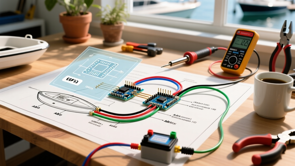

The Critical Importance of a Marine-Grade Blueprint
Designing and installing a reliable marine electrical system is one of the most demanding DIY projects a boat owner can undertake. Unlike automotive or residential environments, a marine vessel is subjected to constant vibration, high humidity, saltwater corrosion, and UV degradation. Relying on a generic schematic is a recipe for stray current corrosion, voltage drop, and potentially catastrophic electrical fires. To ensure safety and compliance, you must develop a comprehensive boat electrical wiring diagram tailored specifically to your vessel's unique layout and load requirements.
This step-by-step walkthrough will guide you through auditing your electrical loads, selecting ABYC-compliant components, drafting your schematic, and executing the physical installation with professional-grade techniques.
Phase 1: The Load Audit and Power Budget
Before drawing a single line on your boat electrical wiring diagram, you must calculate your total DC power budget. This determines your battery bank capacity, alternator output requirements, and main feeder wire gauge.
Calculating Continuous and Intermittent Loads
Divide your devices into two categories: continuous (running for 3+ hours, like navigation lights or cabin fans) and intermittent (bilge pumps, horn, windlass). Below is a reference table for common modern marine electronics and their average amp draws on a 12V DC system.
| Marine Device (2026 Standard Models) | Average Amp Draw (12V DC) | Load Type | Recommended Circuit Protection |
|---|---|---|---|
| Garmin GPSMAP 8616xsv Chartplotter | 3.5A (Max 4.5A) | Continuous | 7A Blade Fuse |
| Standard Horizon GX2400 VHF Radio | 1.5A (Rx) / 6.0A (Tx) | Intermittent | 10A Blade Fuse |
| Rule 2000 GPH Bilge Pump | 8.4A (Running) | Intermittent | 10A or 15A Fuse (Direct to switch) |
| Lewmar V3 Windlass | 70A - 130A (Under load) | Intermittent | 110A Circuit Breaker |
| LED Navigation Light Kit (Aqua Signal) | 0.8A (Total combined) | Continuous | 3A Blade Fuse |
ABYC E-11 Standard Note: The American Boat & Yacht Council (ABYC) mandates that overcurrent protection must be sized based on the wire's ampacity, not just the device's draw. Always cross-reference your fuse size with the maximum allowable ampacity of the wire gauge you select. For deeper compliance details, refer to the ABYC Standards portal.
Phase 2: Wire Sizing and Component Selection
Marine environments demand tinned copper wire. Untinned automotive wire will oxidize and turn black (copper oxide is an insulator) within a single season in saltwater. As of 2026, premium marine-grade tinned wire (such as Ancor or Pacer) costs roughly $1.80 to $2.80 per foot depending on the AWG.
The 3% Voltage Drop Rule
Wire gauge is determined by the total circuit length (positive + negative wire run), the maximum current, and the allowable voltage drop. For critical electronics and navigation lights, the ABYC dictates a maximum 3% voltage drop. For general cabin loads (lights, wipers), a 10% drop is acceptable.
Example Calculation: If your VHF radio draws 6A and is located 15 feet from the distribution panel, the total round-trip wire length is 30 feet. To maintain a 3% drop (0.36V on a 12V system), a 12 AWG wire is technically sufficient, but stepping up to 10 AWG provides a safer buffer for voltage sags during engine cranking.
Core Component Checklist
- Main Distribution Panel: Blue Sea Systems ST Blade Fuse Block (Model 5025 for 12 circuits, approx. $65). Features independent negative buses and clear dust covers.
- Battery Switch: Blue Sea 7195 e-Series (approx. $85). Rated for 350A continuous, allowing you to isolate the house bank from the start bank.
- Terminals: Adhesive-lined heat shrink ring terminals (Ancor or 3M). The inner meltable adhesive creates a waterproof seal that prevents wicking corrosion.
Phase 3: Drafting the Boat Electrical Wiring Diagram
With your components selected, it is time to draft the schematic. You can use software like SmartDraw, Lucidchart, or even a large sheet of drafting paper. A proper boat electrical wiring diagram must include the following standardized elements:
- Power Sources: Clearly label the House Battery Bank, Start Battery, Alternator, and Shore Power Charger.
- Main Fusing: Show the main Class T fuses located within 7 inches of the battery positive terminal (an ABYC requirement if the wire is not fully sheathed).
- Switches and Relays: Map out battery isolators, Automatic Charging Relays (ACRs), and manual switch panels.
- Color Coding: Adhere to marine color codes. DC Positive is universally Red. DC Negative is Yellow (or Yellow with a red stripe per updated ABYC E-11 guidelines, though Black is still widely accepted on older schematics).
- Grounding Points: Identify the DC negative bus bar and the hull grounding point for lightning protection and radio RF grounding.
Phase 4: Step-by-Step Execution Walkthrough
Translating your boat electrical wiring diagram into physical reality requires meticulous attention to chafe protection and termination techniques.
Step 1: Mounting the Core Infrastructure
Mount your Blue Sea ST Blade fuse block and negative bus bar in a dry, accessible location above the bilge line. Use stainless steel screws (#10 or #12) and apply a dab of marine sealant (like 3M 4200) to the threads to prevent moisture ingress into the core of fiberglass bulkheads.
Step 2: Routing and Looming
Never run DC positive and DC negative wires in the same bundle without separation, and keep them at least 12 inches away from high-voltage AC shore power lines to prevent electromagnetic interference (EMI) with sensitive NMEA 2000 networks. Route all wires through split corrugated wire loom to protect against chafing against fiberglass edges and aluminum stringers.
Step 3: Professional Crimping
Soldering is strictly prohibited for primary marine wire connections by the ABYC, as solder creates a rigid point that will fracture under engine vibration. Instead, use a high-quality ratchet crimper (such as the Knipex 97 52 64 or a dedicated Selkirk marine crimper).
- Strip the wire using a precision wire stripper to avoid nicking the copper strands.
- Insert the wire into the adhesive-lined heat shrink terminal until it bottoms out.
- Crimp using the correct die size on your ratchet tool. The tool will not release until the exact compression pressure is achieved.
- Apply heat with a heat gun (not a lighter) starting from the middle of the barrel and moving outward until the adhesive oozes slightly from the ends.
Common Failure Modes and Troubleshooting
Even with a perfect boat electrical wiring diagram, physical installation errors can lead to system failures. Watch out for these specific edge cases:
Stray Current Corrosion
If a DC positive wire chafes against a wet bilge or an ungrounded metal engine block, current leaks into the water, rapidly destroying underwater metals like propellers and thru-hulls. Fix: Install a dedicated DC leakage monitor or ensure all bilge areas are bone-dry and wires are elevated on cable clamps.
The "Loose Negative" Ghost Fault
Many DIYers obsess over positive connections but neglect the negative bus. A loose negative connection increases resistance, causing voltage drops that mimic a failing battery or a dead alternator. Fix: Torque all bus bar nuts to the manufacturer's specification (typically 40-50 in-lbs for 1/4" brass studs) and apply a light coating of anhydrous dielectric grease to prevent oxidation.
Final Verification and Sea Trial
Before launching, perform a continuity test on every circuit using a digital multimeter. Verify that the voltage at the furthest device (e.g., the masthead navigation light) does not drop more than 3% from the battery voltage when the circuit is active. For further safety guidelines and mandatory equipment checklists, always consult the U.S. Coast Guard Boating Safety division and review practical installation case studies via BoatUS Expert Advice.
By strictly adhering to your custom boat electrical wiring diagram and utilizing marine-grade components, you ensure your vessel remains powered, safe, and compliant for years of reliable service on the water.