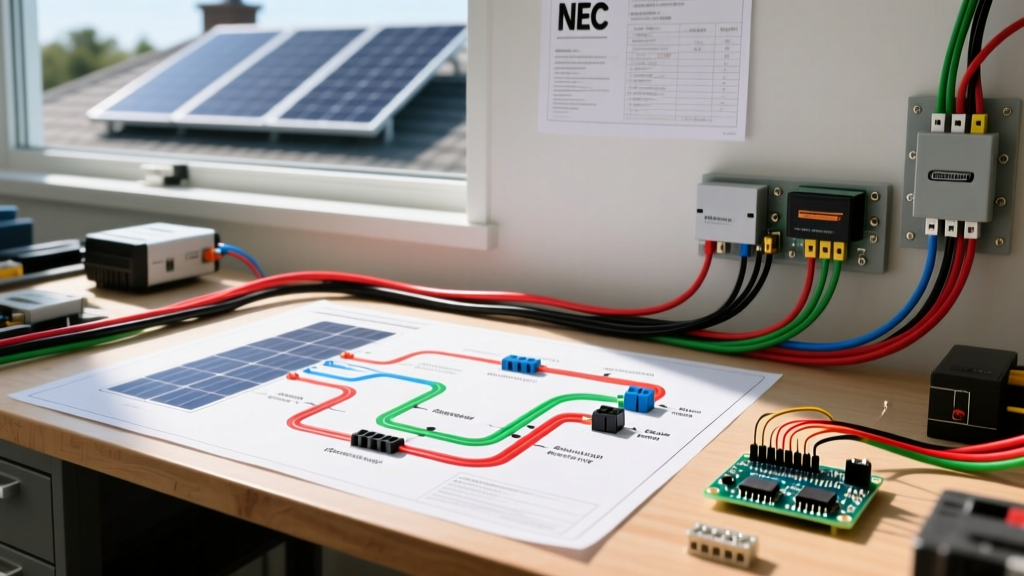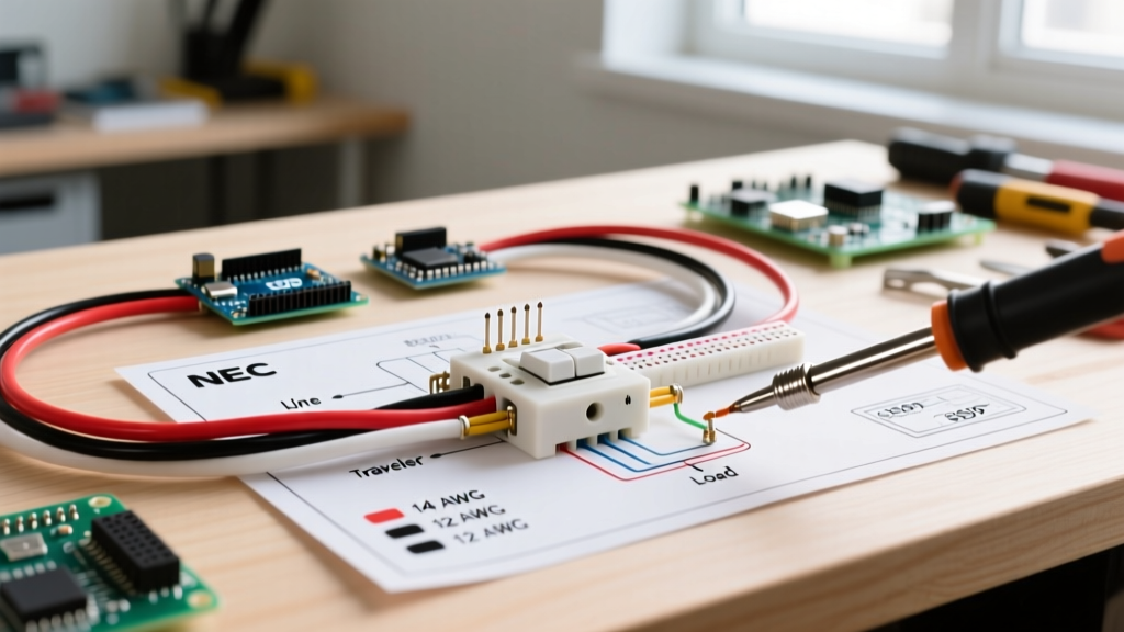

Understanding the 3-Way Switch Circuit Topology
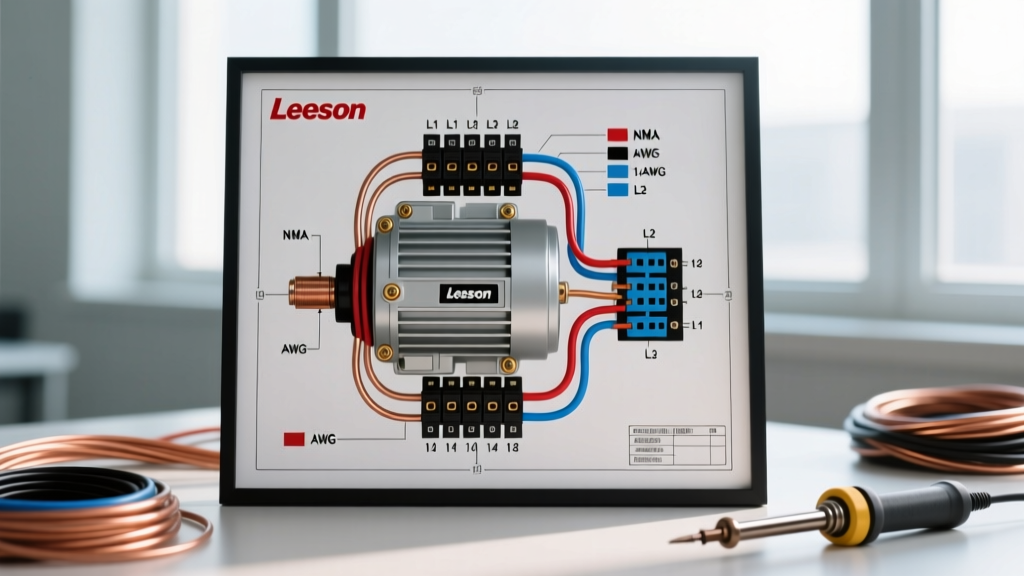
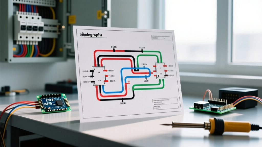
Unlike standard single-pole switches that simply interrupt a single hot wire, a 3-way switch system allows you to control a single lighting load from two separate locations. This requires a specialized circuit topology utilizing two 3-way switches, a continuous hot (line) conductor, a load conductor, and two 'traveler' wires that bridge the two switches. When interpreting 3 way wiring diagrams for switches, the most common point of failure isn't the switch mechanism itself, but the misidentification of traveler, line, and neutral conductors, or the use of improper wire gauges for the circuit's amperage.
In 2026, with the proliferation of smart home ecosystems, understanding the physical layer of your switch wiring is more critical than ever. Modern smart 3-way switches require a neutral wire at the switch box to power their internal Wi-Fi or Zigbee radios. If your existing wiring lacks this neutral, or if the wire gauge is undersized for the run length, you will experience voltage drop, flickering LEDs, or complete smart-switch failure.
Wire Gauge (AWG) Selection Matrix for 3-Way Circuits
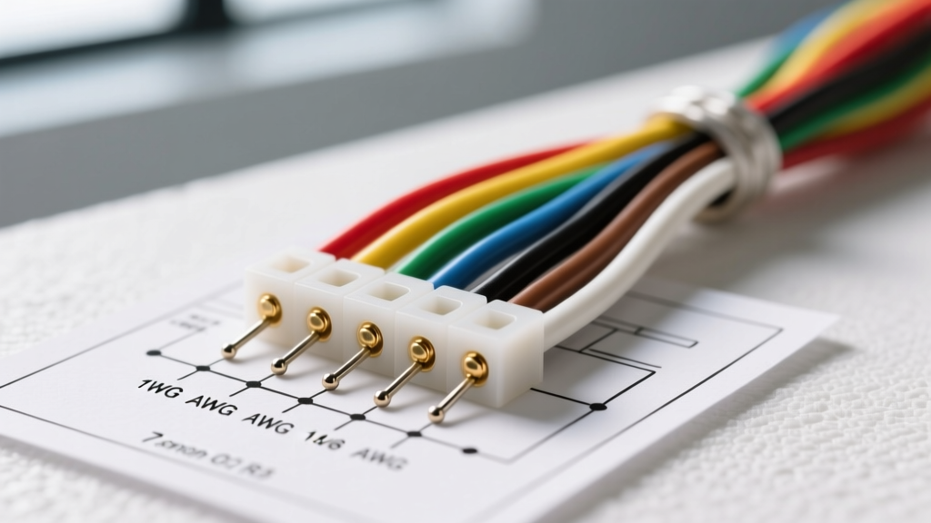
Selecting the correct American Wire Gauge (AWG) is strictly governed by the rating of the circuit breaker protecting the branch circuit. According to the National Electrical Code (NFPA 70), the wire's ampacity must meet or exceed the breaker's rating. However, for long 3-way switch runs—common in large hallways, staircases, or detached garages—voltage drop becomes a primary engineering concern.
| Breaker Size | Minimum Wire Gauge | Recommended Gauge (Runs > 50 ft) | Max Load (120V / 80% Cont.) | Common Application |
|---|---|---|---|---|
| 15 Amp | 14 AWG | 12 AWG | 1,440 Watts | Standard bedroom/hallway lighting |
| 20 Amp | 12 AWG | 10 AWG | 1,920 Watts | Kitchen lighting, garage, outdoor fixtures |
| 30 Amp | 10 AWG | 8 AWG | 2,880 Watts | Heavy commercial lighting arrays (rare in residential) |
Expert Insight: While 14 AWG is legally permissible on a 15-amp breaker, professional electricians almost exclusively pull 12 AWG for all new residential lighting circuits. The marginal increase in copper cost (roughly $15-$25 more per 250ft spool in 2026) is vastly offset by the reduction in voltage drop and the flexibility to upgrade the breaker to 20A in the future without rewiring.
NEC-Compliant Color Coding for Travelers and Neutrals
Adhering to strict color coding standards is not just a best practice; it is a life-safety requirement. The OSHA wiring design and protection standards and the NEC mandate specific colors to ensure future electricians can safely service the circuit.
The Conductor Color Breakdown
- Line (Hot): Black. This is the ungrounded conductor bringing power from the breaker panel to the first 3-way switch.
- Load (Switched Hot): Black or Red. This conductor carries power from the second 3-way switch to the light fixture. It is only energized when the switch circuit is closed.
- Neutral (Grounded Conductor): White or Gray. This completes the circuit back to the panel. It should never be switched or interrupted by the 3-way mechanism.
- Ground (Equipment Grounding Conductor): Bare copper or Green. Bonds all metal boxes and switch yokes to earth ground.
- Travelers: These are the two wires running between the traveler terminals on both 3-way switches. By convention, these are typically Red and Black when using a 3-wire cable (like 12/3 or 14/3 Romex).
Re-identifying White Traveler Wires (NEC 200.7)
In certain dead-end 3-way wiring configurations, you may be forced to use the white wire in a 2-wire or 3-wire cable as a traveler or a hot feed. The NEC strictly prohibits leaving a white wire unmarked if it is being used as an ungrounded (hot) conductor. You must re-identify the white wire at both termination points using black or red electrical tape, or a permanent marker. Failure to do so creates a severe shock hazard for anyone assuming the white wire is a safe neutral.
The 'Neutral at the Switch' Requirement (NEC 404.2(C))
One of the most critical updates in modern electrical codes that affects 3 way wiring diagrams for switches is the requirement for a neutral conductor at the switch box. Older homes often wired 3-way circuits using only hot and traveler wires at the switch locations, bypassing the neutral entirely to save copper.
2026 Code Reality Check: If you are upgrading to smart switches (e.g., Lutron Caseta, Leviton Decora Smart), the master switch requires a constant 120V power source. This requires both a Line (Hot) and a Neutral wire in the same switch box. If your existing 3-way diagram lacks a neutral at the switch, you must either pull new 12/3 or 14/3 cable from the nearest junction box containing a neutral, or utilize specialized 'no-neutral' smart switches that rely on trickle current through the load (which often causes LED ghosting).
Standard vs. Dead-End 3-Way Wiring Topologies
When planning your rough-in, you must choose between the two primary 3-way topologies. The physical layout of your framing and the location of your power source dictate which diagram you must follow.
1. The Standard Configuration (Power at First Switch)
This is the most intuitive and common layout. Power from the panel enters the first switch box. A 3-wire cable (Black, Red, White, Bare) runs from the first switch to the second switch, acting as the travelers and a neutral pass-through. Finally, a 2-wire cable runs from the second switch up to the light fixture.
- Box 1: Receives Line (Black) and Neutral (White). Black connects to the Common terminal. Red and Black (from 3-wire) connect to Travelers.
- Box 2: Red and Black (from 3-wire) connect to Travelers. The Common terminal connects to the Black wire running up to the light fixture (Load).
2. The Dead-End 3-Way (Power and Load at First Switch)
In this scenario, both the power source and the light fixture are located at the first switch box. The second switch is a 'dead-end'—it only receives the traveler wires and no permanent neutral or load.
- Box 1: Line, Load, and Neutral are all present. A 3-wire cable runs to Box 2. The White wire is re-identified with black tape and used as the second traveler.
- Box 2: Only receives the Red and Black (re-identified White) travelers. Note: Because there is no neutral at Box 2, you cannot install a smart switch at this location without rewiring.
Real-World Failure Modes and Troubleshooting
Even with perfect 3 way wiring diagrams for switches, field errors occur. Here is how to diagnose the most frequent 3-way circuit failures using a digital multimeter (DMM).
Failure Mode A: Lights Only Turn On When Switch 1 is UP
The Symptom: The circuit behaves like a single-pole switch. Switch 2 does nothing unless Switch 1 is in a specific position.
The Cause: The Line or Load wire has been mistakenly connected to a Traveler terminal instead of the Common (usually the dark-colored or odd-colored screw) terminal.
The Fix: Identify the Common terminal on the misbehaving switch. Move the single hot/load wire to the Common screw, and place the two remaining wires on the brass Traveler screws.
Failure Mode B: LED Fixtures Flicker or Glow When OFF
The Symptom: The lights are technically off, but emit a faint glow or strobe every few seconds.
The Cause: This is rarely a switch wiring error. It is usually caused by installing non-dimmable LEDs on a circuit with a smart switch that leaks a small amount of standby current through the load to power its internal radio, or by induced phantom voltage from running 14 AWG traveler wires parallel to high-voltage appliance lines over long distances.
The Fix: Install an Lutron LUT-MLC (Minimum Load Capacitor) across the load at the fixture, or upgrade the wire gauge to 12 AWG to reduce capacitive coupling.
Failure Mode C: Breaker Trips Instantly Upon Energizing
The Symptom: The moment you flip the breaker on, it trips with a loud pop.
The Cause: A direct short. In 3-way circuits, this almost always happens at the light fixture box where a wire nut connecting the neutral bundle has loosened, allowing the bare copper ground wire to touch the black load wire. Alternatively, the white neutral wire was mistakenly used as a traveler and capped with a hot wire.
The Fix: Isolate the circuit. Open all junction boxes and verify that no ground wires are touching ungrounded conductors, and verify all white wires are strictly bonded to other white/neutral wires.
Final Verification Checklist
Before closing up your drywall or screwing on your faceplates, run through this mandatory verification sequence:
- Verify all ground wires are bonded to metal boxes (using a 10-32 green grounding screw) and to the switch yokes.
- Confirm that no white neutral wires are connected to the brass traveler terminals.
- Ensure any white wire used as a hot or traveler is wrapped in black or red electrical tape at the termination point.
- Tug-test every wire nut connection. A loose neutral on a multi-wire branch circuit (MWBC) can result in 240V being sent to your 120V fixtures, instantly destroying them.