
Why Generic Diagrams Fail Custom Auto Installations
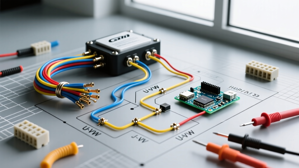
As we navigate the complex electrical architectures of 2026 vehicles, relying on a generic auto electrical wiring diagram is a recipe for catastrophic failure. Modern trucks, SUVs, and passenger cars no longer use simple point-to-point 12V analog wiring. Instead, they rely on multiplexed networks like CAN-bus, LIN-bus, and FlexRay to manage everything from headlight pulses to fuel injection. When planning a custom installation—whether it is a high-draw LED light bar, a dual-battery isolator for overlanding, or an electric winch—misinterpreting the factory wiring schematic can lead to backfed voltage, fried Electronic Control Units (ECUs), and electrical fires.
This installation planning guide moves beyond basic theory. We will break down how to properly decode manufacturer schematics, calculate precise voltage drops, select the correct automotive-grade wire insulation, and integrate aftermarket relays without triggering modern Body Control Module (BCM) fault codes.
Decoding the Auto Electrical Wiring Diagram: SAE vs. DIN Standards
Before cutting a single wire, you must identify the diagramming standard your vehicle manufacturer uses. North American vehicles typically follow SAE (Society of Automotive Engineers) conventions, while European and Asian imports often lean toward DIN (Deutsches Institut für Normung) standards. Confusing the two is a common edge case that leads to miswired grounds and reversed polarity.
| Component | SAE Standard (US/Domestic) | DIN Standard (European/Import) |
|---|---|---|
| Ground / Earth | Open triangle or chassis line | Terminal 31 (Solid line to chassis) |
| Switch (SPST) | Open gap with hinged line | Terminal 15 (Switched ignition) |
| Relay Coil | Rectangle with diagonal line | Terminals A1 / A2 or 85 / 86 |
| Constant Battery | Unswitched 12V+ line | Terminal 30 (Direct battery) |
| Ignition Switched | Key symbol or 'IGN' label | Terminal 15 (Ignition on) |
According to the SAE J1128 standard for low-tension primary cable, wire color coding is strictly regulated for specific circuits (e.g., yellow for ABS, light green for right turn signals). However, in custom installs, you should always use a multimeter to verify the diagram's claims, as previous owners or dealership service departments frequently deviate from factory color codes.
Pre-Installation Load Calculation Matrix
A critical step in interpreting an auto electrical wiring diagram is determining if the existing circuit can handle your new accessory. Most modern BCMs monitor current draw on individual circuits. If you tap into a 10A fuse circuit to power a 15A accessory, the BCM will detect the overcurrent and permanently disable that circuit to protect the silicon, requiring a dealership flash to reset.
Use the matrix below to plan your wire gauge and fuse sizing based on continuous draw and peak draw. Note that these calculations assume TXL (Thin Wall) wire routed through an engine bay with ambient temperatures up to 125°C.
| Accessory Type | Continuous Draw | Peak Draw | Min. Wire Gauge (TXL) | Recommended Fuse (ATO/ATC) |
|---|---|---|---|---|
| LED Light Bar (40-inch) | 12A | 14A | 14 AWG | 15A Mini |
| 12V Air Compressor | 25A | 40A (Startup) | 10 AWG | 40A ATC |
| Electric Winch (12,000 lb) | 150A | 350A (Stall) | 1/0 AWG | 250A MEGA Fuse |
| Aftermarket Horns | 8A | 12A | 16 AWG | 10A Mini |
For high-current protection, standard blade fuses are insufficient. We recommend utilizing Littelfuse MEGA or MIDI fuses for any circuit exceeding 80A. As detailed in the Littelfuse automotive fuse guidelines, high-amperage fuses require specific torque values on their mounting bolts to prevent arcing and localized melting.
Step-by-Step Routing & Relay Integration Strategy
When the auto electrical wiring diagram dictates the use of a relay to isolate high-current loads from delicate dashboard switches, proper component selection and routing are paramount.
- Select the Correct Relay: Avoid cheap, unbranded 4-pin relays. Use a standard ISO mini relay like the Bosch JD1912-12V-40A. For modern vehicles with sensitive ECUs, you must use a relay with an internal diode or resistor across the coil (pins 85 and 86) to suppress the inductive voltage spike that occurs when the magnetic field collapses.
- Choose Automotive-Grade Wire: Never use THHN building wire or standard PVC hook-up wire under the hood. Use TXL or GXL wire. TXL features a thin-wall cross-linked polyethylene (XLPE) insulation that withstands 125°C and resists automotive fluids.
- Terminate with Waterproof Connectors: Crimp connections in the engine bay must use sealed connectors. The Deutsch DT series is the industry standard for waterproof, multi-pin connections, while heat-shrink butt splices with adhesive-lined tubing are mandatory for single-wire splices.
- Wrap and Secure the Harness: Ditch the cheap plastic split-loom tubing. Wrap your custom harness in Tesa 51036 PET fleece automotive harness tape. This tape prevents wire chafing, eliminates harness rattle, and withstands engine bay heat without turning into a sticky mess.
Common Failure Modes & Edge Cases in 12V Systems
The CAN-Bus Trap: Never use a standard 'T-tap' or 'vampire' splice on twisted-pair CAN-bus wires to get a switched 12V signal. Doing so alters the characteristic impedance of the network, causing communication errors across the vehicle. Always use an inductive clamp or a dedicated CAN-bus isolation module to read network signals without physical splicing.
Voltage Drop: The Silent Killer
Even if your auto electrical wiring diagram shows the correct wire gauge, excessive routing length will cause voltage drop. A 12V compressor receiving only 10.5V at its terminals will draw significantly more amperage to produce the same mechanical work, leading to overheated wires and melted connectors. The Fluke electrical troubleshooting resources emphasize that testing voltage drop under load is the only accurate way to verify circuit health. A healthy circuit should exhibit less than 0.1V drop per connection and less than 0.5V total drop from the battery to the load.
Ground Loop Interference
When installing aftermarket audio or sensitive sensor arrays, grounding different components to different chassis points can create a ground loop. This occurs when there is a slight voltage potential between two ground points, causing current to flow through the RCA shield wires. Always establish a single, centralized star-ground point for sensitive electronics, sanding away paint and clear coat to bare metal, and sealing the connection with dielectric grease.
Essential Tools for Diagram Verification
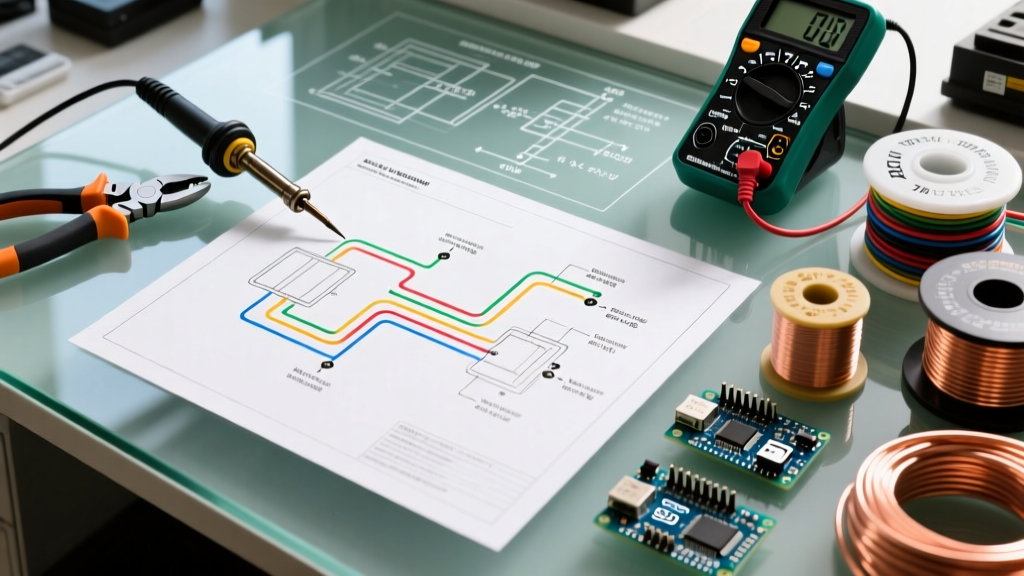
You cannot plan an installation based solely on paper. You must verify the physical reality of the vehicle against the schematic. Equip your bench with the following:
- Fluke 87V Industrial Multimeter: The auto-ranging feature and high-impedance inputs prevent ghost voltage readings when probing modern multiplexed circuits.
- Power Probe IV: Allows you to inject power and ground directly into a component to bypass the vehicle's wiring, instantly verifying if a motor or solenoid is mechanically sound before you spend hours tracing a diagram.
- Wire Tracer / Tone Generator: Essential for identifying where a specific wire in the cabin bundle terminates in the engine bay firewall grommet.
Frequently Asked Questions
Can I use a factory auto electrical wiring diagram for a different trim level?
Proceed with extreme caution. A base-model truck and a fully loaded Platinum trim of the same year will have vastly different wiring harnesses. The higher trim may include additional modules, different ground locations, and upgraded alternators. Always verify your specific VIN's build sheet against the schematic.
Why does my custom relay click rapidly when the switch is turned on?
This is known as 'relay chatter' and is almost always caused by a severe voltage drop on the trigger circuit. The relay coil is not receiving enough voltage to fully close the internal contacts, causing it to bounce. Check your trigger wire gauge and ensure the dashboard switch is not corroded.
Is it safe to upgrade a factory fuse to a higher amperage for a new accessory?
Absolutely not. The factory fuse is sized to protect the specific gauge of wire and the internal traces of the BCM or fuse block. Upgrading a 10A fuse to a 20A fuse to stop it from blowing means the wire will now melt and potentially catch fire before the fuse blows. Always run a new, independently fused circuit directly from the battery for high-draw accessories.