
The Engineering Logic Behind Ford's Fender-Mounted Solenoid
Unlike General Motors and Chrysler, which historically integrated the starter solenoid directly onto the starter motor housing, Ford engineered a unique fender-mounted starter solenoid (often technically classified as a heavy-duty starter relay) for decades. This design choice was not arbitrary; it was a deliberate thermal and electrical isolation strategy. By mounting the solenoid on the inner fender well, Ford kept the high-amperage switching mechanism away from the extreme radiant heat of the exhaust manifolds and engine block. Furthermore, this setup allowed the heavy-gauge battery cables to remain live only up to the fender well, keeping the undercarriage wiring safer and simplifying the routing to the starter motor itself.
Whether you are restoring a classic 1960s Mustang, maintaining a 1980s F-150 with a 300 inline-six, or wiring a custom hot rod, understanding the exact wiring diagram for Ford starter solenoid configurations is critical. A miswired control circuit will result in a no-crank condition, while undersized main power cables will cause severe voltage drop, prematurely destroying your starter motor.
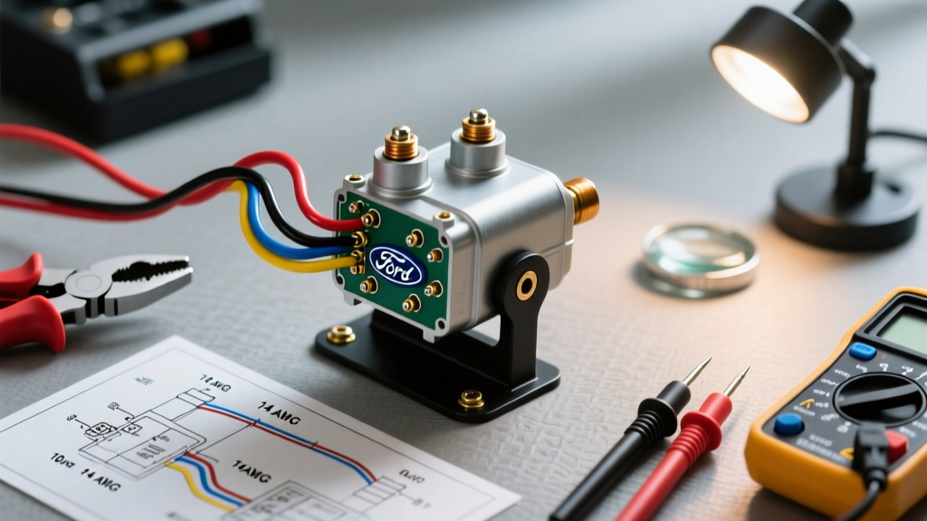
Decoding the Terminals: B, M, S, and I
Before cutting any wire or crimping any ring terminals, you must understand the terminal designations found on OEM and aftermarket replacements like those manufactured by Standard Motor Products (SMP). Misidentifying these posts is the leading cause of DIY wiring harness fires.
- B (Battery) Terminal: The primary high-current input. This connects directly to the positive battery post via a heavy-gauge cable. It is constantly live (hot at all times).
- M (Motor) Terminal: The high-current output. This connects directly to the starter motor's main lug. It only carries current when the solenoid is energized and the internal copper contact disc bridges the B and M terminals.
- S (Start/switch) Terminal: The low-current control input. This is a male spade terminal that receives 12V from the ignition switch's 'Start' position. This energizes the internal electromagnetic coil, pulling the plunger to bridge B and M.
- I (Ignition) Terminal: Found only on 4-post solenoids. This provides a 12V bypass feed directly to the ignition coil's positive terminal during cranking, compensating for the voltage drop across the ballast resistor in older points-style ignition systems.
3-Post vs. 4-Post Solenoid Comparison Matrix
Selecting the correct solenoid depends entirely on your vehicle's ignition architecture. Below is a functional comparison to guide your parts selection.
| Feature | 3-Post Solenoid (e.g., SMP SS-588) | 4-Post Solenoid (e.g., SMP SS-581) |
|---|---|---|
| Terminals Present | B, M, S | B, M, S, I |
| Ignition Type | EFI, Duraspark, or Electronic Ignition | Points Condenser / Early Ballast Systems |
| Coil Bypass Required? | No | Yes (during cranking only) |
| I-Terminal Output | N/A | 12V Hot only while key is in 'START' |
Step-by-Step Wiring Execution & Cable Sizing
Adhering to SAE International Standards for automotive wire ampacity is non-negotiable when dealing with starter circuits that can pull 250 to 400 amps under load.
1. Main Power Circuit (B and M Terminals)
For standard V8 applications (up to 350 cubic inches), use 2 AWG SGT (Standard Gauge Thermoplastic) or 2 AWG SXL (Cross-Linked) pure copper battery cable. For high-compression engines, diesel swaps, or extreme cold-weather applications, upgrade to 1/0 AWG.
- Strip exactly 5/8 inch of insulation from the cable ends.
- Use a mechanical or hydraulic crimper to attach heavy-duty copper ring terminals (3/8 inch inner diameter for standard Ford studs).
- Apply adhesive-lined, dual-wall heat shrink tubing over the crimp barrel. The inner adhesive layer melts to create a waterproof seal, preventing green corrosion (copper oxide) which acts as a massive electrical resistor.
- Route the B cable from the battery positive terminal. Route the M cable from the solenoid down to the starter motor.
- Torque the 3/8-inch terminal nuts to 7 to 10 ft-lbs. Over-torquing can snap the solenoid's internal copper stud; under-torquing creates arcing and heat.
2. Control Circuit (S Terminal)
The S terminal requires far less current—typically under 15 amps. Use 10 AWG or 12 AWG primary wire (GXL or TXL insulation rating). Route this wire through the firewall to the ignition switch's 'Start' (S) terminal. Always install a 20-amp inline fuse or utilize a factory fusible link near the firewall connection to protect against a short-to-ground in the engine bay.
3. The Ignition Bypass (I Terminal - 4-Post Only)
If utilizing a 4-post solenoid on a classic points-ignition vehicle, run a 14 AWG wire from the 'I' terminal to the positive side of the ignition coil. Crucial Warning: This wire must never be connected to a constant 12V source, or the coil will overheat and fail when the key is in the 'Run' position.
The PMGR Mini-Starter Swap Edge Case
A highly common modern modification is swapping a heavy, obsolete Ford starter for a lightweight 90s-era PMGR (Permanent Magnet Gear Reduction) mini-starter. PMGR starters feature their own integrated, on-motor solenoid. This creates a 'dual solenoid' wiring scenario that confuses many DIYers.
Expert Wiring Rule for PMGR Swaps: When retaining the fender-mounted Ford solenoid to trigger a PMGR mini-starter, the fender solenoid acts strictly as a heavy-duty relay. You must wire the mini-starter's own 'S' spade terminal directly to the mini-starter's main 'B' lug using a short 10 AWG jumper wire. The fender solenoid's 'M' terminal will then only supply the heavy amperage to the starter's main lug, while the jumper wire ensures the on-motor solenoid engages simultaneously.
Load Testing & Voltage Drop Diagnostics
If your engine clicks but fails to crank, do not immediately condemn the starter or solenoid. According to Fluke Automotive Testing Guides, a voltage drop test is the only scientifically valid method to diagnose high-resistance faults in the starter circuit.
- Set your digital multimeter to the DC Millivolts (mV) setting.
- Place the red probe directly on the solenoid's 'B' terminal stud (not the wire ring terminal, the actual metal stud).
- Place the black probe directly on the solenoid's 'M' terminal stud.
- Have an assistant crank the engine.
- Interpretation: A healthy solenoid will show a voltage drop of less than 0.2V (200mV) across the main contacts. If your meter reads 0.5V or higher, the internal copper contact disc is pitted, carbon-fouled, or welded, and the solenoid must be replaced.
Common Failure Modes & Safety Protocols
Understanding how these components fail is critical for workshop safety and vehicle reliability.
- Welded Contacts (Run-On): The most dangerous failure mode occurs when the high-amperage arcing literally melts and welds the internal copper disc to the B and M terminals. The starter will continue to crank even after you release the key and remove it from the ignition. Immediate Action: Keep a 1/2-inch wrench on the battery terminal at all times during initial testing to physically disconnect the ground if the starter hangs.
- Parasitic Draw from Frayed S-Wire: If the insulation on the 10 AWG S-wire chafes against the fender apron, it can create a high-resistance short. This may not blow the fuse but will provide enough stray voltage to partially energize the solenoid coil, causing a rapid 'machine-gun' clicking sound and severe battery drain overnight.
- Coil Collapse (Internal Break): The internal electromagnetic coil can break due to thermal cycling. In this scenario, the S-terminal will receive a perfect 12V signal (verifiable with a test light), but the plunger will not pull. This requires complete solenoid replacement, as the coil is potted in resin and non-serviceable.
By adhering to these precise wiring diagrams, torque specifications, and diagnostic protocols, you ensure a robust, reliable starting system capable of handling the immense electrical loads demanded by modern and classic Ford powertrains alike.