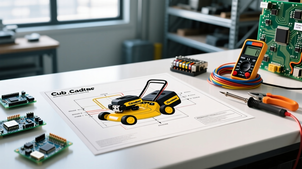

Introduction to the LTX 1050 Electrical System
The Cub Cadet LTX 1050 is a robust lawn tractor powered by a Kohler Courage SV590 engine, but like all modern outdoor power equipment, it relies on a complex network of safety interlocks, relays, and charging circuits. When the tractor fails to crank, the PTO refuses to engage, or the battery drains mid-mow, guessing the cause is a waste of time and money. Using the wiring diagram for Cub Cadet LTX 1050 transforms random part-swapping into targeted, data-driven diagnostics. This guide breaks down the exact schematic pathways, wire color codes, and multimeter testing procedures required to isolate electrical faults on the LTX 1050 platform.
Decoding the MTD/Cub Cadet Color Code Standard
Before probing any connectors, you must understand the standardized wire color coding used by MTD (the parent company of Cub Cadet) for the LTX series. While minor variations exist between manufacturing years, the core harness follows a strict logic:
- Red (RD): Unswitched 12V DC battery positive. Runs directly from the battery to the starter solenoid and the main 20A fuse.
- Black (BK): Chassis ground and battery negative.
- Purple (PU): Starter solenoid trigger signal (12V DC when the key is in the 'START' position).
- Green (GN): Safety interlock circuit pathways (brake, seat, and PTO switches).
- White (WH): Alternator/Stator AC output and voltage regulator inputs.
- Orange (OR): Switched 12V DC power to the PTO clutch and accessory circuits.
- Yellow (YL): Lighting circuits and headlight power.
The Safety Interlock System (No-Crank Diagnostics)
The most common reason an LTX 1050 fails to crank is a fault in the safety interlock circuit. The wiring diagram reveals that the starter solenoid's ground path is not a direct wire to the chassis; instead, it routes through a series of Normally Open (NO) and Normally Closed (NC) microswitches.
Brake and Seat Switch Logic Flow
To complete the starter ground circuit, the following conditions must be met simultaneously according to the schematic:
- The brake pedal must be fully depressed (engaging the brake switch).
- The PTO engagement lever must be in the 'OFF' position.
- The operator must be seated (if the engine is running, or during start-up depending on the specific harness revision).
Troubleshooting Step: Set your digital multimeter (DMM) to continuity mode. Disconnect the wiring harness from the brake pedal switch. With the pedal depressed, you should read near 0.0 ohms (continuity). If the meter reads 'OL' (Open Loop), the internal contacts are corroded or the mechanical plunger is misaligned. Replacement brake switches for the LTX 1050 typically cost between $12 and $18.
Starter Solenoid and Ignition Switch Pinouts
If the interlocks are verified, the next node on the wiring diagram for Cub Cadet LTX 1050 is the ignition switch and starter solenoid. The LTX 1050 uses a 5-pin ignition switch. Here is the exact terminal map you need for voltage drop testing:
- B (Battery): Constant 12V from the main fuse.
- S (Start): Sends 12V to the purple wire (solenoid trigger) only in the 'START' position.
- M (Magneto): Connects to the engine kill wire. Grounded in 'OFF', open in 'RUN' and 'START'.
- A (Accessory): Powers the hour meter or 12V outlet.
- L (Lights): Powers the headlight circuit.
Pro-Tip for Field Testing: If turning the key yields a single loud 'click' but no engine turnover, do not immediately condemn the starter motor. Use the wiring diagram to locate the purple trigger wire on the solenoid. If you measure 12V on the purple wire while holding the key in 'START', the ignition switch and safety interlocks are flawless. The fault lies in the solenoid's internal contacts or a seized starter bendix. A replacement 4-post solenoid costs roughly $22, while a new OEM starter assembly is closer to $135.
PTO Clutch Engagement and Air Gap Calibration
The LTX 1050 utilizes an electromagnetic PTO clutch (typically an Ogura or Warner 5315-series unit). When you pull the PTO knob, 12V DC is routed through a 20A inline fuse and a heavy-duty relay to the clutch coil. If the mower blades refuse to spin, consult the PTO section of the schematic.
Electrical and Mechanical Diagnostics
Before buying a $75 replacement clutch, perform these two critical tests outlined in the service manual:
- Resistance Test: Disconnect the two-pin plug leading to the clutch. Measure the resistance across the clutch terminals. The specification is 2.8 to 3.5 ohms. A reading of 0.0 indicates a shorted coil; 'OL' indicates a broken internal winding.
- Voltage Drop Test: Reconnect the plug, back-probe the connector with the engine running and PTO engaged. You must read a minimum of 11.8V DC. If voltage drops below 11.0V, the issue is a failing relay or corroded harness connectors, not the clutch itself.
- Air Gap Adjustment: Even with perfect electrical readings, the clutch will slip if the mechanical air gap is too wide. Use a feeler gauge to check the gap between the armature and the rotor. Adjust the three perimeter nuts to achieve exactly 0.015" to 0.020".
Kohler SV590 Stator and Voltage Regulator Testing
A frequent complaint with aging LTX 1050 models is a battery that dies after 45 minutes of mowing. The wiring diagram shows the charging circuit originates at the engine stator, passes through the voltage regulator/rectifier, and feeds back to the battery via the ignition switch's 'B' terminal.
The Kohler Courage SV590 stator produces Alternating Current (AC), which the regulator converts to Direct Current (DC). To diagnose a no-charge condition:
- Locate the two white wires exiting the engine blower housing.
- Disconnect the plug and set your DMM to AC Volts.
- Start the engine and run it at full throttle (3600 RPM).
- You must measure 28VAC to 35VAC across the two white stator wires. If you read less than 20VAC, the stator is burned out and requires engine teardown to replace.
- If AC voltage is normal, reconnect the harness and test the DC output at the regulator's center (or red) output wire. You should read 13.8V to 14.4V DC. If AC is good but DC is zero, the voltage regulator has failed (a $40 part).
Multimeter Diagnostic Reference Chart
Keep this quick-reference table in your toolbox when tracing the wiring diagram for Cub Cadet LTX 1050 in the field.
| Component | Test Parameter | Expected Reading | Common Failure Mode |
|---|---|---|---|
| Main Fuse (20A) | Continuity / Voltage Drop | 0.0 Ohms / < 0.1V Drop | Blown due to PTO clutch short or chafed harness. |
| Ignition Switch (S Term) | DC Voltage (Key in START) | 12.0V - 12.6V | Internal contact carbon buildup; requires $15 switch replacement. |
| PTO Clutch Coil | Resistance (Ohms) | 2.8Ω - 3.5Ω | Heat degradation causing open circuit (reads OL). |
| Stator (SV590) | AC Voltage @ 3600 RPM | 28VAC - 35VAC | Melted insulation on stator windings due to overheating. |
| Brake Safety Switch | Continuity (Pedal Depressed) | 0.0 Ohms | Moisture ingress corroding internal copper contacts. |
Advanced Wire Tracing Techniques
When the wiring diagram for Cub Cadet LTX 1050 indicates a path that seems dead, avoid stripping wire insulation to probe. Instead, use the back-probing technique with fine T-pins at the Molex connectors to preserve the factory weather seals. For comprehensive engine-specific electrical tolerances, always cross-reference the tractor schematic with the official Kohler engine service manuals, as the tractor harness only accounts for the external routing.
If you need to source OEM replacement connectors or specific harness pigtails, the official Cub Cadet parts portal provides exploded diagrams that correlate directly to the electrical schematics, ensuring you order the exact pin-and-socket assemblies required for a watertight repair.
Summary
Troubleshooting the Cub Cadet LTX 1050 electrical system is a logical process of elimination. By systematically following the wiring diagram from the battery positive through the safety interlocks, ignition switch, and finally to the starter or PTO clutch, you can isolate faults with 100% accuracy. Rely on your multimeter, respect the specific ohm and voltage thresholds outlined above, and you will restore your mower to peak operational readiness without wasting money on unnecessary replacement parts.