
Understanding the Ceiling Speaker Wiring Diagram: 8-Ohm vs. 70V Systems
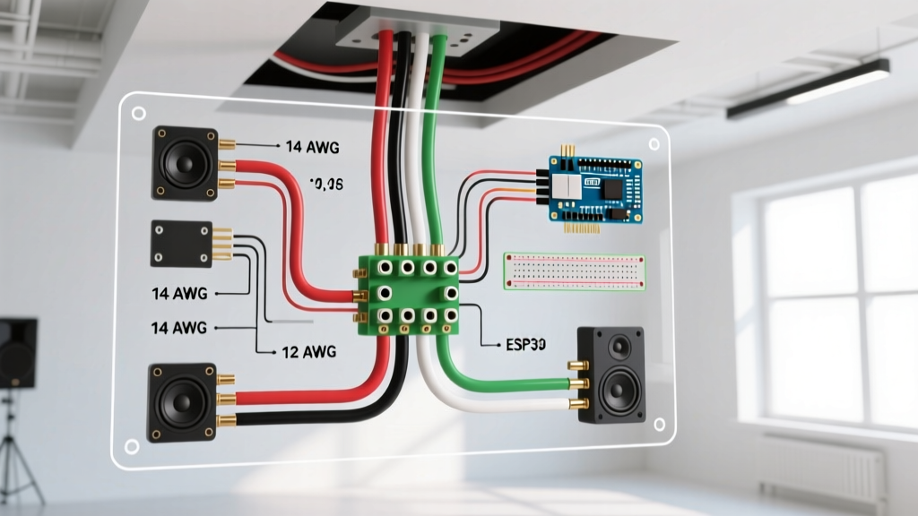
When planning a whole-home audio install or commercial retrofit, the wiring diagram for ceiling speakers is your foundational blueprint. However, not all diagrams are created equal. Before pulling a single foot of cable, you must identify which system architecture your diagram represents: standard low-impedance (8-ohm) or high-impedance distributed (70V/100V).
Residential setups typically utilize 8-ohm speakers, such as the popular Polk Audio RC85i or KEF Ci160QR. In these systems, the wiring diagram must carefully account for impedance drops when wiring multiple speakers to a single amplifier zone. Conversely, commercial environments and large-scale outdoor installs rely on 70V distributed systems (like the JBL Control 24CT). A 70V wiring diagram allows you to daisy-chain dozens of speakers in parallel without the total impedance dropping to dangerous levels that would trigger amplifier protection circuits.
This guide focuses primarily on the most common residential and light-commercial scenario: the low-impedance 8-ohm ceiling speaker wiring diagram, walking you through code compliance, wire selection, and physical termination.
NEC Compliance and Wire Selection (CL2 vs. CL3 vs. CMP)
You cannot simply use standard lamp cord or basic copper wire inside walls and ceilings. The National Electrical Code (NEC / NFPA 70) strictly regulates low-voltage wiring to prevent fire propagation. According to NEC Article 725, speaker wire installed inside residential walls must carry a minimum CL2 (Class 2) rating. However, professional integrators in 2026 almost exclusively specify CL3 (Class 3) rated cable.
Expert Insight: CL2 wire is rated for 150 volts, while CL3 is rated for 300 volts. Because modern high-current Class-D amplifiers can output significant voltage swings during dynamic bass transients, CL3 provides a crucial safety margin and features a thicker, more durable PVC jacket that resists tearing when pulled through tight joist bays.
If your wiring diagram routes cables through a commercial drop-ceiling that doubles as an HVAC return air plenum, you are legally required to use CMP (Plenum-rated) cable. CMP jackets are manufactured from FEP or low-smoke PVC to prevent toxic fume circulation during a fire. Be aware that CMP cable costs roughly 2.5x to 3x more than standard CL3 wire.
2026 Wire Gauge Selection Matrix
Selecting the correct American Wire Gauge (AWG) is critical to preventing frequency loss—specifically the damping factor degradation that ruins bass response. Based on industry standards outlined by resources like the Cerrowire Technical Guidelines, here is the definitive gauge matrix for 8-ohm ceiling speakers:
| Cable Run Distance (One Way) | Recommended AWG (CL3) | Max Power Handling (Est.) | 2026 Avg. Cost per Foot |
|---|---|---|---|
| Under 50 Feet | 16 AWG | 100W | $0.35 - $0.45 |
| 50 to 100 Feet | 14 AWG | 150W | $0.55 - $0.75 |
| 100 to 150 Feet | 12 AWG | 200W+ | $0.90 - $1.20 |
| Over 150 Feet | 10 AWG | 250W+ | $1.50+ |
Note: Always use Oxygen-Free Copper (OFC) rather than Copper-Clad Aluminum (CCA). CCA wire has higher resistance and is prone to galvanic corrosion at the termination points over time.
Step-by-Step Wiring Walkthrough
Step 1: The Rough-In and Routing Rules
Begin by mapping your ceiling speaker locations using a stud finder and a flexible drill bit. When running your 14/2 CL3 speaker wire through the joist bays, you must adhere to separation rules to avoid electromagnetic interference (EMI). Per NEC 725.136, low-voltage audio cables must maintain a minimum 12-inch separation from parallel 120V/240V AC mains wiring (Romex). If your wiring diagram forces the speaker wire to cross an AC line, it must do so at a strict 90-degree angle to minimize the induction of 60Hz hum into the audio signal.
At the speaker cutout location, always leave an 18 to 24-inch service loop of excess wire hanging down. This slack is non-negotiable; it allows you to comfortably terminate the connections, test the speaker before drywall is finished, and easily service the unit years later without needing to fish new wire.
Step 2: Impedance Matching and Diagram Logic
The most common mistake DIYers make when reading a wiring diagram for ceiling speakers is ignoring impedance math. If you wire two 8-ohm speakers in parallel (Positive to Positive, Negative to Negative), the total impedance drops to 4 ohms. While modern amplifiers like the Sonos Amp or WiiM Amp can easily drive 4-ohm loads, older AV receivers will overheat, clip, and shut down.
If you wire them in series (Positive of Amp to Positive of Speaker 1; Negative of Speaker 1 to Positive of Speaker 2; Negative of Speaker 2 back to Amp), the impedance doubles to 16 ohms. This is perfectly safe for the amplifier, but it cuts your power output in half, resulting in a noticeably lower maximum volume.
The Professional Solution: If your diagram calls for four speakers in a single zone, use a Series-Parallel wiring topology. Wire pairs of speakers in series (creating two 16-ohm pairs), and then wire those two pairs in parallel. The final load presented to the amplifier will be a perfectly stable 8 ohms, maximizing power transfer while keeping the amplifier in its optimal thermal range.
Step 3: Speaker Termination and Service Loops
When terminating the wire at the ceiling speaker, precision is key. Use a dedicated wire stripper to remove exactly 7/16-inch to 1/2-inch of the dielectric jacket. Do not use a utility knife, as scoring the copper conductor creates a weak point that will eventually snap under the tension of the speaker's dog-ear mounting clamps.
If your ceiling speakers feature spring-loaded binding posts, insert the twisted bare copper directly. However, if they feature screw-down terminals, we highly recommend crimping on spade lugs or pin ferrules. This prevents stray copper strands from breaking off and causing a short circuit against the speaker's internal crossover network. Furthermore, ensure the polarity is strictly observed: the stripe on the speaker wire must always connect to the positive (+) terminal. Reversing polarity on even one speaker in a multi-speaker zone will cause acoustic phase cancellation, resulting in thin, hollow sound with zero bass impact.
Step 4: Amplifier Termination
At the amplifier or distribution hub, strip the wire and insert it into the binding posts. Tighten the posts firmly, but avoid over-torquing, which can strip the brass threads on cheaper receivers. If you are utilizing a multi-zone distribution block (like those from Niles or Speakercraft), ensure the impedance-matching dip switches on the volume controls are set correctly to protect the amplifier from low-impedance spikes when multiple zones are playing simultaneously.
Troubleshooting Common Wiring Failure Modes
Even with a flawless wiring diagram for ceiling speakers, physical installation errors can cause system failures. Here is how to diagnose the three most common issues:
- Amplifier Goes Into Protect Mode Immediately: This is almost always caused by a short circuit. Inspect your amplifier binding posts for a single, stray strand of copper wire touching the metal chassis or the adjacent negative post. Also, check the ceiling speaker terminals to ensure the dog-ear clamps haven't pinched and pierced the wire jacket, shorting the signal to the metal drywall bracket.
- Persistent 60Hz Hum or Buzz: This indicates a ground loop or EMI induction. Verify that your speaker wire is not running parallel to AC mains, dimmer switches, or fluorescent lighting ballasts. If the hum persists, the issue may be at the amplifier level (ground loop), requiring a ground loop isolator.
- Weak Bass and Hollow Imaging: You have an out-of-phase wiring error. Play a mono, bass-heavy track and stand in the center of the room. If the bass disappears or sounds localized to the walls, one or more speakers have reversed polarity. Use a 9V battery test: briefly touch the battery terminals to the speaker wire. If the speaker cone pushes outward, the polarity is correct. If it sucks inward, the wires are reversed.
Essential Tools for the 2026 Installer
To execute this walkthrough safely and efficiently, ensure your toolkit includes the following:
- Southwire 14/2 CL3 OFC Speaker Wire: The industry standard for reliable, code-compliant in-wall audio.
- Klein Tools 56300 Fish Tape: A 50-foot steel fish tape is essential for navigating insulated joist bays and fire blocks.
- Knipex Precision Wire Strippers: Ensures clean cuts without nicking the copper strands.
- Fluke Pro3000 Tone and Probe Kit: Crucial for identifying and tracing unlabeled wires at the amplifier rack before termination.
For further reading on low-voltage safety standards and insulation ratings, refer to the Underwriters Laboratories (UL) Electrical Safety Resources. By strictly following your wiring diagram, respecting impedance math, and adhering to NEC codes, your ceiling speaker installation will deliver pristine, phase-aligned audio for decades to come.