
Understanding Mini Split Power Topologies
Unlike traditional central air systems that rely on a single high-voltage feed to the outdoor condenser and a separate 120V circuit for the indoor air handler, modern inverter-driven ductless systems utilize a unique power distribution topology. When reviewing a mini split electrical wiring diagram, the first critical distinction is identifying the primary power feed location. In 95% of North American residential installations (including popular 2026 models like the Pioneer WYS series and Mitsubishi MSZ-FS), the main 208/230V power is fed directly to the outdoor condenser. The indoor unit is then powered via a low-voltage communication cable that also carries a stepped-down DC power signal.
However, some 115V ultra-quiet bedroom models (typically 9,000 BTU) reverse this topology, requiring the main branch circuit to terminate at the indoor head first. Always verify the physical schematic located on the inside of the outdoor unit's electrical service panel cover before pulling wire.
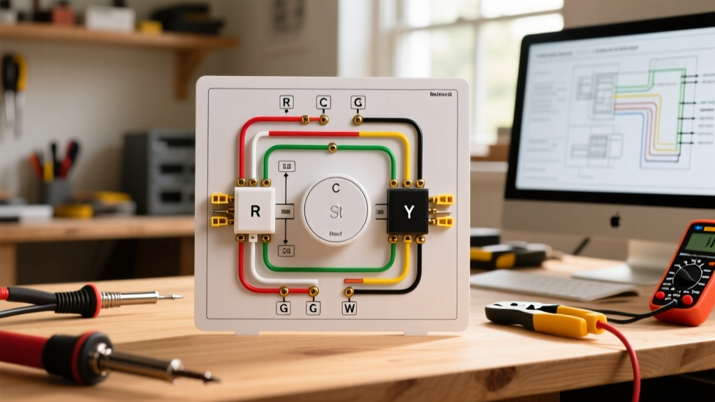
Decoding the Terminal Block Pinouts
The terminal block on a mini split condenser is the nerve center of the system. Misinterpreting these labels is the leading cause of blown control boards and communication faults. Below is the standard pinout reference for 208/230V inverter systems.
| Terminal Label | Function | Voltage / Signal Type | Standard Wire Color (US) |
|---|---|---|---|
| L1 | Main Power Line 1 | 208-230V AC | Black |
| L2 | Main Power Line 2 | 208-230V AC | Red |
| S | Communication / Signal | Pulsed DC (24V-150V) | Blue or Yellow |
| N | Neutral (115V Models Only) | 115V AC | White |
| G / ⏚ | Equipment Ground | 0V (Fault Path) | Green / Bare Copper |
Expert Warning: Never swap L1 and L2 on systems that explicitly label them for specific internal transformer taps, though most modern 230V inverter compressors are phase-agnostic. More importantly, never connect the 'S' (Signal) terminal to a standard 24V AC thermostat wire. Doing so will instantly destroy the indoor unit's EEPROM chip.
Wire Gauge and Breaker Sizing Matrix
Sizing the branch circuit correctly requires looking at the manufacturer's specified MOP (Maximum Overcurrent Protection) and MCA (Minimum Circuit Ampacity). As of 2026, the shift toward A2L mildly flammable refrigerants (like R-32 and R-454B) has slightly increased compressor startup amperages in some 24,000 BTU+ units, making strict adherence to breaker sizing vital to prevent nuisance tripping.
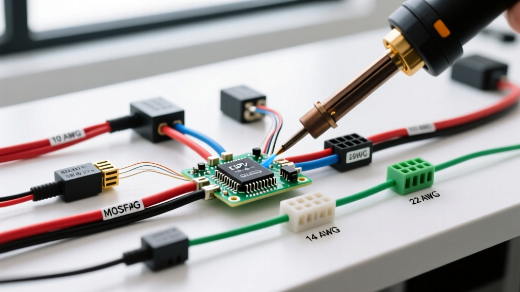
| System Capacity (BTU) | Voltage | Min. Wire Gauge (Copper) | MOP Breaker Size | Disconnect Rating | Est. 2026 Wire Cost (250ft) |
|---|---|---|---|---|---|
| 9,000 - 12,000 | 230V | 14 AWG (Stranded) | 15A (HACR) | 30A / 600V | $85 - $110 |
| 18,000 | 230V | 12 AWG (Stranded) | 20A (HACR) | 30A / 600V | $115 - $145 |
| 24,000 - 36,000 | 230V | 10 AWG (Stranded) | 30A (HACR) | 60A / 600V | $160 - $210 |
The Critical Role of the Communication Wire (S-Terminal)
The most misunderstood element of any mini split electrical wiring diagram is the communication wire. Modern inverters do not use simple on/off 24V signals. The 'S' terminal carries a high-speed, pulsed DC serial communication protocol that allows the indoor thermistor to dictate compressor speed adjustments up to 120 times per minute.
- The EMI Threat: Running unshielded communication wire parallel to the 230V power lines creates Electromagnetic Interference (EMI). This manifests as E1, E2, or U4 communication errors on the indoor display, causing the system to shut down randomly.
- The Solution: You must use 14/4 or 18/4 shielded stranded HVAC cable. The shielding includes a bare copper drain wire. This drain wire must be grounded to the chassis ground screw at the outdoor unit only. Grounding it at both ends creates a ground loop that will fry the control board.
Step-by-Step Termination Procedure
Poor terminations cause high resistance, leading to melted terminal blocks and arc faults. Follow this exact procedure for the outdoor condenser:
- Strip Length: Strip exactly 16mm (5/8 inch) of insulation from the stranded wire. Stripping it too short leaves exposed copper outside the terminal; stripping it too long risks a short circuit against the adjacent terminal.
- Ferrule Crimping: Because mini split terminals use rising-clamp screw designs, inserting raw stranded wire often results in splayed strands. Crimp a 16mm insulated bootlace ferrule onto each wire end before insertion.
- Torque Specification: Tighten the terminal screws using a calibrated torque screwdriver set to 1.2 to 1.5 Nm (Newton-meters). Overtightening strips the brass threads; undertightening causes micro-arcing under load.
- Strain Relief: Secure the cable to the chassis strain relief clamp. The outer jacket of the cable must extend 10mm past the clamp to prevent the internal wires from bearing the weight of the cable run.
NEC Compliance and Disconnect Requirements
According to NEC Article 440 (Air-Conditioning and Refrigerating Equipment), a disconnecting means must be located within sight from, and readily accessible from, the outdoor unit. 'Within sight' is strictly defined by the National Electrical Code as no more than 50 feet away with a direct, unobstructed line of sight.
For mini splits, a 2-pole, 600VDC-rated NEMA 3R outdoor pull-out disconnect is the industry standard. Even if your system only draws 12 amps and uses a 15A breaker, installing a 30A or 60A rated disconnect enclosure provides the physical mass and arc-quenching clearance required for safe outdoor operation. The EPA Energy Star guidelines for ductless heat pumps also heavily emphasize proper electrical isolation to ensure long-term inverter board survival during grid surges.
Common Wiring Faults and Multimeter Diagnostics
When a newly wired mini split fails to power on or throws a fault code, use a digital multimeter (DMM) to isolate the issue systematically:
- Fault: Indoor unit completely dead. Check the 'S' terminal at the outdoor unit. If you read 0V DC between L2 and S, the outdoor control board's step-down transformer or relay has failed. If you read a pulsing DC voltage (fluctuating between 24V and 150V), the outdoor board is fine, and the fault lies in the communication wire or the indoor display board.
- Fault: Breaker trips instantly upon energizing. This is almost always a ground fault or a swapped L1/Ground wire at the disconnect. Verify continuity between the ground bus and the condenser chassis before resetting the HACR breaker.
- Fault: Compressor hums but won't spin (Rare on Inverters). Check for voltage drop. If the line set exceeds 50 feet, voltage drop on 14 AWG wire can starve the inverter's PFC (Power Factor Correction) circuit. Upsize to 12 AWG for runs between 50 and 75 feet, referencing the manufacturer's official installation manuals for exact voltage drop compensation tables.
Mastering the mini split electrical wiring diagram is less about memorizing colors and more about understanding the digital communication topology and strict termination tolerances. By utilizing shielded cabling, precise torque values, and NEC-compliant disconnects, you ensure the system operates at peak SEER2 efficiency for its entire 15-to-20-year lifespan.