
Pre-Installation Planning & Code Compliance
Upgrading or installing a bathroom exhaust system requires more than just mounting a box to the ceiling drywall. As of the 2026 NEC adoption cycle, bathroom electrical circuits are heavily regulated due to the convergence of high moisture, water sources, and electrical current. Before pulling any wire, you must understand the foundational requirements that dictate your wiring diagram for bathroom fan and light configurations.
According to the National Fire Protection Association (NFPA) NEC guidelines, all 120-volt, single-phase, 15- and 20-ampere branch circuits supplying outlets in dwelling unit bathrooms must have Arc-Fault Circuit Interrupter (AFCI) protection. Furthermore, if your fan is installed directly over a bathtub or shower stall, the unit must be GFCI protected and explicitly UL-listed for 'wet locations.' Standard 'damp location' ratings are insufficient for direct shower exposure. Always verify the UL sticker on the fan housing before rough-in.
Calculating CFM and Make-Up Air Requirements
A common failure point in DIY installations is undersizing the fan or ignoring make-up air. The Home Ventilation Institute (HVI) and the U.S. Department of Energy (DOE) ventilation standards recommend a minimum of 1 CFM per square foot of bathroom area. For a 90-square-foot bathroom, you need a 90 CFM fan. However, if you are installing a high-capacity fan (over 200 CFM), you must plan for mechanical make-up air to prevent negative pressure, which can cause backdrafting from water heaters or fireplaces.
- Standard Bathrooms (Under 100 sq ft): 80-110 CFM fan.
- Large Master Baths (100-200 sq ft): 150-200 CFM fan, or dual zone fans.
- Ducting Rule: Never use flexible vinyl or foil ducting. Use 4-inch rigid galvanized steel. Deduct 3 feet of maximum run length for every 90-degree elbow. Keep total runs under 15 feet to maintain static pressure.
Core Wiring Diagram for Bathroom Fan and Light
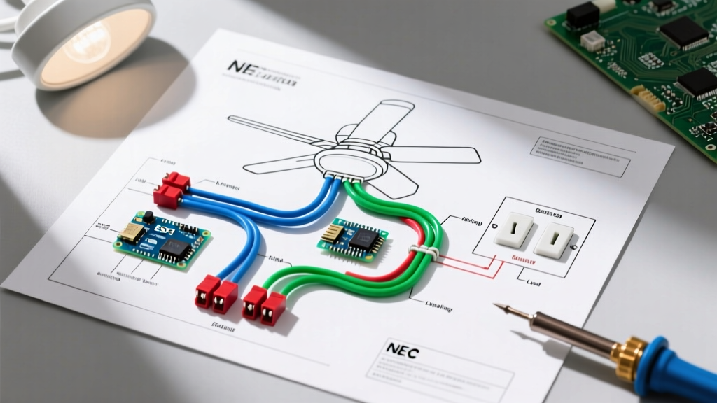
There are two primary ways to wire a combination fan and light unit. Your choice depends on user preference and the existing switch box configuration. Below are the schematic logic flows for both scenarios.
Scenario A: Single Switch Control (Fan & Light Together)
This is the simplest configuration, often used in half-baths or small powder rooms where turning on the light naturally necessitates ventilation.
Wire Required: 14/2 NM-B (for 15A circuits) or 12/2 NM-B (for 20A circuits).
Switch Type: Single-pole 15A or 20A toggle/rocker.
- Power Source to Switch: The hot (black) wire from the breaker panel enters the switch box and connects to the bottom brass terminal of the single-pole switch.
- Switch to Fan/Light Unit: A 2-wire cable runs from the switch to the ceiling junction box. The switched hot (black) connects to the black wire on the fan/light unit.
- Neutral Bundle: All white neutral wires (source, outgoing, and fixture) are wire-nutted together in the ceiling box.
- Grounding: All bare copper grounds are pigtailed and bonded to the green ground screw on the switch and the green ground screw on the fan housing.
Scenario B: Dual Switch Control (Independent Operation)
This is the modern standard for full bathrooms, allowing the user to turn on the light without engaging the noisy fan, or to leave the fan running after turning off the light.
Wire Required: 14/3 NM-B or 12/3 NM-B from the switch box to the ceiling unit.
Switch Type: Single-gang duplex switch (two independent switches in one yoke) or a double-gang box with two single switches.
- Power Source to Switch: The incoming hot (black) wire is pigtailed to both brass terminals on the duplex switch.
- Travelers to Ceiling: The 3-wire cable (Black, Red, White, Bare) runs from the switch to the ceiling. The black wire connects to the light switch load terminal; the red wire connects to the fan switch load terminal.
- Ceiling Terminations: In the fan housing, the black wire from the 3-wire cable connects to the light fixture lead. The red wire connects to the fan motor lead.
- Neutral & Ground: The white wire in the 3-wire cable is capped off in the switch box (unless you are using a smart switch or timer that requires a neutral). In the ceiling box, the incoming neutral and the fixture neutral are bundled together.
Material & Component Selection Matrix (2026 Market)
Selecting the right hardware prevents callbacks and ensures quiet operation. Below is a comparison of top-tier 2026 units and essential rough-in materials.
| Component / Model | Specs & Features | Avg. Cost (2026) | Best Application |
|---|---|---|---|
| Panasonic WhisperCeiling FV-0511VQ1 | 110 CFM, 0.3 Sones, ECM Motor, SmartFlow tech | $145 - $160 | Master baths requiring ultra-quiet operation |
| Broan-NuTone Roomside Series | 110 CFM, 1.0 Sones, Retrofit friendly, TrueSeal damper | $175 - $195 | Retrofits where attic access is restricted |
| Homewerks 7117-01-BN | 110 CFM, Bluetooth speaker, LED light integrated | $130 - $150 | Budget smart-bathroom upgrades |
| 12/3 NM-B Romex (Solid Copper) | 20A rated, 3 conductors + ground, PVC jacket | $0.95 / linear ft | 20A bathroom receptacle/lighting shared circuits |
| 4' Rigid Galvanized Duct | Smooth interior, prevents condensation buildup | $18 - $24 / 5ft stick | All exhaust runs (Code compliant) |
Step-by-Step Rough-In and Wiring Execution
Follow this sequence to ensure a clean, inspection-ready installation.
- Locate and Cut (15 mins): Find ceiling joists spaced 16 inches on-center. Cut the drywall hole using the provided template. If you are between joists, install 2x4 blocking to mount the fan bracket securely.
- Mount the Housing (20 mins): Secure the fan housing to the joist or blocking using the provided lag screws. Do not rely on drywall anchors; the vibration from the motor will eventually crack the drywall.
- Run the Ducting (30 mins): Attach the 4-inch rigid metal duct to the fan collar using aluminum foil tape (never standard cloth duct tape, which degrades in humidity). Route the duct to the exterior soffit or roof cap, sloping it slightly downward toward the exterior to prevent interior condensation drip.
- Pull the Wire (20 mins): Fish the 14/3 or 12/3 NM-B cable from the switch box to the ceiling hole. Leave exactly 12 inches of slack inside the ceiling box and 8 inches inside the switch box. Staple the wire within 8 inches of the switch box as per NEC 334.30.
- Terminate and Test (15 mins): Make your wire connections using IDEAL SureWire connectors or standard wire nuts. Torque the breaker terminal to the manufacturer's specification (usually 20-25 in-lbs) using a torque screwdriver to prevent arc faults.
Troubleshooting Common Wiring Faults
Even with a perfect wiring diagram for bathroom fan and light setups, physical installation variables can cause issues. Here is how to diagnose the most common 2026 field failures:
- Fan Hums but Blower Wheel Doesn't Spin: This is rarely a wiring fault. It usually indicates a failed start capacitor on the motor board or physical debris blocking the squirrel cage. If using an older AC motor fan, replace the capacitor. If using a modern ECM motor (like the Panasonic Whisper series), the internal control board may have suffered a voltage spike; check for proper grounding.
- LED Light Flickers on Dimmer Switch: Many combination units feature integrated LED arrays that are not compatible with standard leading-edge triac dimmers. You must use a trailing-edge (ELV) dimmer specifically rated for low-wattage LED loads (e.g., Lutron Diva DVELV-300P).
- Condensation Dripping from Fan Grille: This is a ducting failure, not an electrical one. It occurs when warm, moist bathroom air hits cold flexible ducting in an unconditioned attic. Replace flex duct with rigid metal and insulate the exterior of the duct with R-8 fiberglass duct wrap.
Expert Planning Takeaway
A successful bathroom ventilation project hinges on the planning phase. By selecting an Energy Star-certified ECM fan, utilizing 12/3 NM-B wire for future-proofing, and strictly adhering to rigid ducting standards, you eliminate 95% of common post-installation complaints. Always map out your specific wiring diagram for bathroom fan and light circuits on paper before making your first drywall cut, ensuring your switch box has adequate cubic inch volume to accommodate the extra conductors required for independent fan and light control.