
Mastering the John Deere LT155 Electrical Wiring Diagram
The John Deere LT155 remains one of the most robust lawn tractors ever produced, frequently equipped with the legendary 15 HP Kawasaki FD440V liquid-cooled V-twin engine. As these machines continue to operate well into 2026, their electrical systems—specifically the starter motor circuits and Power Take-Off (PTO) clutches—become primary failure points due to harness degradation, vibration-induced micro-fractures, and corrosion. Understanding the John Deere LT155 electrical wiring diagram is not just about tracing lines; it is about comprehending the logical flow of current through safety interlocks, high-amperage solenoids, and inductive motor loads.
Unlike modern tractors that rely on complex CAN-bus networks, the LT155 utilizes a straightforward, analog 12V DC architecture. This makes it an ideal platform for DIY motor wiring tutorials and foundational electrical diagnostics. In this comprehensive guide, we will dissect the starter motor circuit, the PTO clutch engagement loop, and the critical safety interlock module, providing you with exact specifications, real-world failure modes, and actionable testing procedures.
Decoding the LT155 Wire Color Standards
Before probing any connectors, you must understand the John Deere color-coding standard used in the LT155 harness. Deviating from these standards during a repair can lead to catastrophic short circuits or bypassed safety mechanisms.
- Red: Unswitched 12V+ battery power (Constant hot).
- Black: Chassis ground or negative return path.
- Yellow: Starter solenoid engagement signal (Switched 12V+).
- White: Accessory circuits, including the PTO clutch power supply.
- Green/Orange: Safety interlock module signals and switch returns.
The Starter Motor Circuit: High-Amperage Architecture
The starter motor on the Kawasaki FD440V is typically a Denso or Mitsubishi gear-reduction unit designed to draw between 150 and 200 amps under peak cranking load. The John Deere LT155 electrical wiring diagram routes this massive current through a heavy-duty 10 AWG cable, bypassing the ignition switch entirely to prevent thermal melting.
Tracing the Cranking Path
When you turn the ignition key to the 'Start' position, the following sequence occurs:
- Ignition Switch (B to S Terminal): 12V+ flows from the main 30A fuse to the 'B' (Battery) terminal. Turning the key bridges the internal contacts, sending a low-amperage signal (approx. 2-4 amps) out of the 'S' (Start) terminal via a yellow wire.
- Starter Solenoid Activation: This yellow wire connects to the small 'S' spade terminal on the starter solenoid. The solenoid's internal coil energizes, creating a magnetic field that pulls the heavy copper contact disc inward.
- High-Current Transfer: The copper disc bridges the two large terminals on the solenoid. 12V+ from the battery (via a 10 AWG red cable) is now routed directly to the starter motor's main post.
- Motor Engagement: The starter motor's internal bendix gear engages the flywheel ring gear, cranking the engine.
Common Starter Circuit Failure Modes
If the LT155 exhibits a 'single click but no crank' symptom, the issue is rarely a dead battery. More often, it is a voltage drop across the solenoid contacts. Over thousands of cycles, the internal copper disc develops a carbon layer, increasing resistance. In 2026, a replacement OEM-style solenoid costs between $25 and $45, while a complete aftermarket Denso-style starter motor ranges from $110 to $160.
PTO Clutch and Safety Interlock Diagnostics
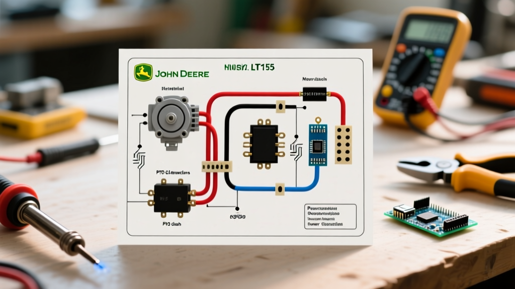
The LT155 uses an electrically actuated PTO clutch (typically manufactured by Warner Electric or Ogura) rated for 150 ft-lbs of torque. This clutch relies on an electromagnetic coil that draws approximately 3.5 to 4.0 amps when engaged. According to Warner Electric's technical documentation, the internal coil resistance of a healthy 12V PTO clutch should measure strictly between 3.5 and 4.5 ohms at room temperature.
The Interlock Logic Module
The PTO circuit is governed by a solid-state Time Delay Module (TDM). The TDM monitors the seat switch, the brake pedal switch, and the PTO dash switch. If the operator stands up while the PTO is engaged and the brake is not depressed, the TDM interrupts the ground path to the PTO relay within 2 seconds, killing power to the clutch coil. Bypassing this module is not only a severe safety hazard but can also cause voltage spikes that destroy the ignition module's diodes.
Step-by-Step Motor Wiring Troubleshooting Matrix
Use the following diagnostic matrix to isolate electrical faults based on the specific behavioral symptoms of your LT155.
| Symptom | Probable Cause | Diagnostic Step & Expected Value |
|---|---|---|
| Rapid clicking at solenoid; no crank | Severe voltage drop on positive cable or weak battery cell | Measure voltage at solenoid battery post during crank. Must remain above 10.5V. |
| Silent turn of key; no click | Blown 30A main fuse, failed ignition switch, or open safety brake switch | Check for 12V at ignition 'B' terminal. Check continuity through brake switch when depressed. |
| PTO clutch fails to engage; dash light on | Open coil winding in PTO clutch or failed TDM ground output | Disconnect clutch plug. Measure resistance across clutch pins. Expected: 3.5Ω - 4.5Ω. |
| PTO clutch drags or slips under load | Low voltage to clutch due to corroded harness pins or worn clutch armature | Measure voltage at clutch connector while running. Must be within 0.5V of battery voltage. |
| Engine continues to crank after key release | Solenoid contacts welded together due to high-current arcing | Disconnect battery immediately. Replace solenoid; inspect starter motor draw for shorts. |
The Critical Role of Voltage Drop Testing
Many DIY mechanics rely solely on multimeters to check for 12V presence, completely missing the phenomenon of voltage drop. A wire with only two strands of copper intact out of forty will still show 12V on a digital multimeter when no load is applied. However, when the starter motor demands 180 amps, that damaged wire will act as a massive resistor, dropping the voltage to 6V and stalling the motor.
Expert Diagnostic Rule: Always test circuits under load. As detailed in Fluke's authoritative guide on voltage drop testing, a healthy high-amperage starter circuit should exhibit less than 0.5V total drop on the positive side and less than 0.2V on the ground side during active cranking. Set your multimeter to DC Volts, place the red probe on the battery positive post, and the black probe directly on the starter motor casing while an assistant cranks the engine.
Wire Gauge Selection and Harness Repair Standards
When repairing the John Deere LT155 electrical wiring diagram, selecting the correct wire gauge and insulation type is paramount. The vibration profile of a single-cylinder or V-twin lawn tractor is incredibly harsh, capable of shaking standard butt-connectors loose within a single mowing season.
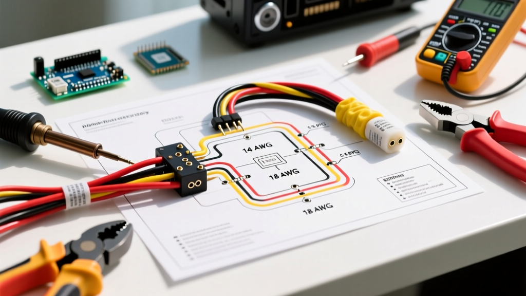
- Starter & Battery Cables: Use strictly 10 AWG or 8 AWG stranded copper wire. Insulation must be rated for high heat (cross-linked polyethylene or XLPE is preferred over standard PVC).
- PTO Clutch & Accessory Circuits: 14 AWG is the standard. Do not use 16 AWG, as the 4-amp continuous draw over a 6-foot run will introduce unacceptable voltage drop, leading to premature clutch slip and burnout.
- Safety Interlock Signals: 16 AWG or 18 AWG is sufficient for low-current switch signals.
For all splices, abandon standard vinyl electrical tape and crimp-only connectors. Use adhesive-lined, dual-wall heat shrink tubing. The inner layer of hot-melt adhesive melts and flows into the wire strands, creating a waterproof seal that prevents the green copper oxide corrosion that plagues older LT155 harnesses. For connector pins, always use a proper ratcheting crimp tool (such as the Titan 11510 or equivalent) to ensure a gas-tight mechanical bond.
Sourcing OEM vs. Aftermarket Components in 2026
As the LT155 ages, sourcing original John Deere wiring harnesses (Part Number AM127324 or similar variations depending on the exact serial number break) can be cost-prohibitive, often exceeding $180 if still in stock. For localized repairs, building a custom pigtail using SAE J1128 compliant primary wire is the most economical and reliable approach. You can reference Kawasaki's official engine manual repository for specific terminal torque specs on the FD440V starter and alternator posts, ensuring you do not strip the soft aluminum threads on the engine block grounding points.
By treating the John Deere LT155 electrical wiring diagram as a logical map rather than a mere illustration, you can systematically eliminate variables, accurately diagnose motor and clutch faults, and restore your tractor to factory-level reliability for years to come.