
Upgrading 12V Camper Van Auxiliary Lighting
As the DIY Class B camper van and overland trailer market continues to mature in 2026, builders are moving away from simplistic, single-light circuits toward more sophisticated, zoned lighting layouts. Whether you are installing dual 10W exterior LED awning pods, a pair of interior reading lamps, or twin 12V marine spotlights, controlling multiple fixtures from a single centralized point is a fundamental requirement. Finding a reliable and safe wiring diagram for one switch and two lights is essential for managing these 12V DC auxiliary circuits without running redundant switch loops or overloading your vehicle's fuse block.
Unlike residential 120V AC wiring, 12V DC vehicle systems demand strict attention to voltage drop, wire gauge sizing, and vibration-resistant termination methods. In this comprehensive vehicle-specific guide, we will break down the exact schematic, component sizing, and ABYC-compliant crimping standards required to wire two 12V lights to a single rocker switch in an RV, camper van, or boat.
Bill of Materials & Component Sizing
Before cutting any wire, you must calculate your total amperage draw to properly size your fuse and conductors. For this guide, we are using two 10W 12V LED lights. Total wattage is 20W. Using Ohm's Law (Current = Power / Voltage), a 20W load on a 12V system draws approximately 1.67 Amps. While 18 AWG wire could technically handle this current, the marine and RV industry standard dictates a minimum of 14 AWG for mechanical durability and to mitigate voltage drop over long wire runs inside a vehicle chassis.
| Component | Specification | Brand/Model Example | Est. Cost (2026) |
|---|---|---|---|
| Primary Wire | 14 AWG Stranded Marine Copper | Ancor / Windy Nation | $0.85 / ft |
| Rocker Switch | SPST 3-Terminal (with LED indicator) | Carling V-Series 20A | $14.50 |
| Fuse | 5A ATO/ATC Blade Fuse | Blue Sea Systems | $1.20 |
| Terminals | 14-16 AWG Heat Shrink Ring/Spade | Ancor Marine Grade | $0.45 / ea |
| Connectors | 14-16 AWG Heat Shrink Butt Splice | Blue Sea / Ancor | $0.60 / ea |
The Physics: Why Parallel Routing is Mandatory
When executing a wiring diagram for one switch and two lights in a 12V DC environment, the lights must be wired in parallel. If you mistakenly wire the two LED fixtures in series, the 12V system voltage will divide equally across the two loads, delivering only 6V to each fixture. Because modern 12V LED drivers require a minimum threshold voltage to fire, both lights will either remain completely dark or emit a severe, unusable flicker. Furthermore, in a series circuit, if one LED driver fails open, the entire circuit breaks, killing power to the second light. Parallel wiring ensures that both lights receive the full 12V (minus minimal voltage drop) simultaneously and operate independently of each other's internal failures.
Step-by-Step Routing: The 12V Schematic
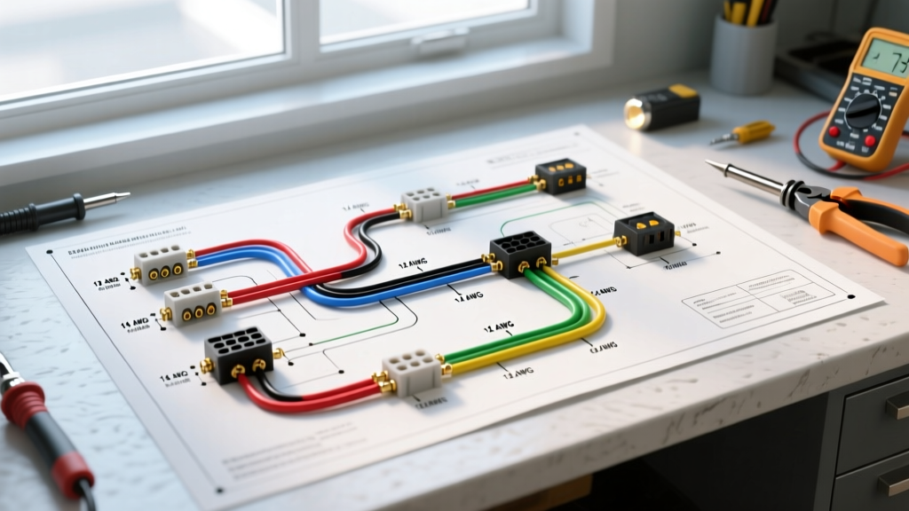
Below is the exact routing sequence for a standard 12V vehicle auxiliary lighting circuit. This assumes you are utilizing a centralized positive and negative bus bar system, which is the gold standard for modern camper van electrical builds.
Phase 1: Power and Fusing
Power originates from your vehicle's 12V auxiliary battery bank or the load side of your main DC breaker. From the positive bus bar, route a 14 AWG red wire to your fuse block. Insert a 5A ATO blade fuse. While 14 AWG wire is rated for up to 15A-20A depending on the insulation type, we use a 5A fuse to protect the downstream 1.67A load and the switch contacts. According to Blue Sea Systems' fusing guidelines, the fuse should be sized as close to the continuous load as possible while still allowing for minor inrush currents, which LED drivers occasionally exhibit upon startup.
Phase 2: The Carling Rocker Switch Pinout
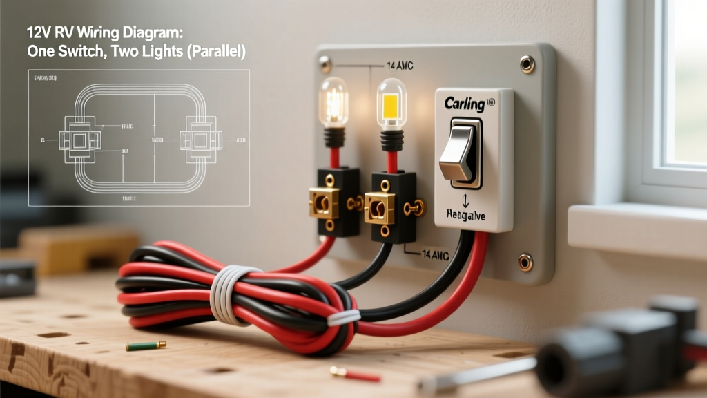
From the load side of the 5A fuse, run a 14 AWG red wire to the back of your dashboard or control panel. Most high-end RV builds utilize the Carling V-Series Contura Rocker Switches. For a simple on/off operation with an illuminated indicator, you need an SPST (Single Pole, Single Throw) switch with 3 terminals. The pinout is as follows:
- Terminal 1 (Line): Connect the incoming 12V positive wire from the fuse block here.
- Terminal 2 (Load): Connect the outgoing 14 AWG red wire heading toward the lights here.
- Terminal 3 (Ground): Connect a 14 AWG black wire from this terminal to your negative bus bar. This completes the circuit solely for the switch's internal LED indicator light. If you skip this, the switch will still turn the exterior lights on and off, but the rocker face will not illuminate when active.
Phase 3: The Parallel Split and Grounding
Run the outgoing positive wire from Terminal 2 to the physical location of your lights. To create the parallel split, you will use a marine-grade heat-shrink butt connector to join the main positive feed to two separate 14 AWG pigtail wires—one for each light's positive terminal. Alternatively, use a sealed 3-way Deutsch connector or a WAGO 221 lever nut (if housed in a dry, accessible junction box) to split the feed.
For the ground path, run a 14 AWG black wire from the negative terminal of Light A and Light B back to a centralized negative bus bar. Never rely on chassis grounding in modern unibody camper vans or composite trailers. Chassis grounding introduces unpredictable resistance, galvanic corrosion risks, and severe voltage drop, which leads to premature LED driver failure.
Expert Voltage Drop Calculation: Let us calculate the voltage drop for a 15-foot one-way wire run using 14 AWG copper (approx. 2.525 ohms per 1,000 ft). The formula is: VD = (2 x Length x Current x Resistance) / 1000.
VD = (2 x 15 x 1.67 x 2.525) / 1000 = 0.12 Volts.
A 0.12V drop on a 12V system is exactly 1%, which is well below the 3% maximum threshold recommended by marine wire and cable selection standards. Your lights will operate at peak luminosity.
Common Failure Modes & Troubleshooting
Even with a perfect schematic, environmental factors in vehicles can cause electrical gremlins. Here is how to diagnose the most common issues associated with this specific circuit:
- Switch LED Glows Dimly When OFF: This occurs if the Line and Load terminals on the rocker switch are reversed, or if there is a high-resistance fault on the negative bus bar allowing phantom voltage to backfeed through the switch's internal indicator LED. Swap the wires on Terminals 1 and 2 to resolve.
- Lights Flicker at Idle: If the lights flicker when the vehicle engine is idling but stabilize when driving, your alternator is likely outputting 14.4V, and the cheap LED drivers in your fixtures lack adequate PWM filtering. Upgrade to LEDs with integrated constant-current drivers rated for 10V-30V DC.
- One Light is Noticeably Dimmer: This indicates a high-resistance connection on the positive split. Inspect your butt splices. If you used a non-ratcheting crimper, the copper strands may not be fully compressed inside the barrel, creating a localized hot spot and voltage drop. Cut and re-crimp using a heat-shrink butt splice and a ratcheting tool.
Marine-Grade Crimping Standards
In a vibrating vehicle environment, solder-only connections are prone to brittle fracture due to work hardening. The ABYC (American Boat & Yacht Council) E-11 standard strictly mandates the use of mechanical crimps for all DC wiring. When terminating your 14 AWG wires to the Carling switch spades or the ring terminals for the bus bar, always use adhesive-lined heat shrink terminals. Apply heat with a precision hot air gun set to 350°F until the adhesive sealant extrudes slightly from the edges of the shrink tubing. This creates a waterproof, gas-tight seal that prevents oxygen and moisture from causing green copper oxidation inside the crimp barrel, ensuring your auxiliary lighting circuit remains reliable for the lifespan of the vehicle.