
Decoding the 2 Speed Electric Fan Wiring Diagram
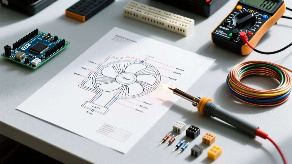
When integrating a multi-speed motor into a residential or commercial electrical system, understanding the underlying schematic is non-negotiable. A standard 2 speed electric fan wiring diagram typically governs a Permanent Split Capacitor (PSC) motor or a shaded-pole motor. Unlike single-speed setups that rely on a simple line-and-neutral connection, 2-speed PSC motors utilize multiple winding taps to alter the magnetic field strength, thereby changing the motor's RPM.
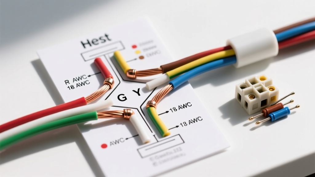
In most fractional-horsepower 2-speed fans (ranging from 1/10 HP to 1/2 HP), the wiring diagram will feature at least four primary conductors exiting the motor housing:
- Line (L1 / Hot): The main power feed, usually black or red.
- Neutral (N): The return path, strictly white or gray.
- High-Speed Tap: Often blue, connecting to the main winding for maximum torque and RPM.
- Low-Speed Tap: Often yellow or brown, routing through an intermediate winding coil to increase impedance and drop the speed.
- Ground (G): Bare copper or green, bonding the motor casing to the equipment grounding conductor (EGC).
According to the U.S. Department of Energy's Motor Systems guidelines, PSC motors are favored for their reliability and lack of a centrifugal start switch, but they demand precise voltage delivery. A voltage drop of just 10% can cause a 2-speed fan to stall on its low-speed tap, leading to rapid winding overheating and eventual insulation breakdown.
Panel Integration: Sizing Breakers for Motor Inrush
The most common mistake DIYers and novice electricians make when following a 2 speed electric fan wiring diagram is sizing the branch circuit breaker based solely on the motor's Full Load Amps (FLA). Motors are inductive loads; they require a massive surge of current—known as Locked Rotor Amps (LRA) or inrush current—to overcome initial inertia.
Under NFPA 70 (National Electrical Code) Article 430, the branch circuit short-circuit and ground-fault protective device (the breaker) is permitted to be sized significantly higher than the motor's FLA to prevent nuisance tripping during startup. For an inverse-time standard thermal-magnetic breaker, the NEC allows sizing up to 250% of the FLA for AC motors.
Breaker and Wire Gauge Sizing Matrix
| Motor Size (HP) | Voltage | Approx. FLA | Est. Inrush (LRA) | NEC Max Breaker | Recommended Breaker | Min. Wire Gauge |
|---|---|---|---|---|---|---|
| 1/10 HP | 120V | 2.5A | 12A | 15A | 15A (Standard) | 14 AWG Copper |
| 1/4 HP | 120V | 5.8A | 28A | 15A | 15A or 20A | 14 AWG (15A) / 12 AWG (20A) |
| 1/3 HP | 120V | 7.2A | 38A | 20A | 20A | 12 AWG Copper |
| 1/2 HP | 120V | 9.8A | 55A | 25A | 20A or 25A | 12 AWG or 10 AWG |
Note: Always defer to the motor manufacturer's nameplate data. If the nameplate specifies a 'Max Fuse' or 'Max Breaker' rating, that value supersedes standard NEC tables.
Step-by-Step: Routing from the Panel to the Speed Switch
Proper execution of the 2 speed electric fan wiring diagram requires a dedicated switch rated for motor loads. Standard lighting dimmers use triacs that chop the AC sine wave, which will rapidly destroy a fan motor's windings. You must use a stepped motor speed control switch (e.g., the Leviton 1722-0W 3-position fan speed control).
- Panel Termination: At the main or sub-panel, strip the 12/2 NM-B (Romex) cable jacket leaving at least 1/4 inch of insulation entering the panel clamp. Strip exactly 3/4 inch of insulation from the black and white conductors. Torque the breaker terminal screw to the manufacturer's specification (typically 12 to 14 in-lbs for a standard 20A Square D QO or Homeline breaker) to prevent arcing and thermal creep.
- Switch Box Wiring: Route the 12/2 cable to the switch box. The black (hot) wire connects to the LINE terminal on the speed switch. The white (neutral) wire must be pigtailed and wire-nutted directly to the motor's neutral lead; it does not pass through the speed switch.
- Switch to Fan Routing: Run a 12/3 or 14/3 cable (depending on breaker size) from the switch box to the fan canopy. Connect the black wire to the switch's HIGH terminal, and the red wire to the LOW terminal. The white wire serves as the shared neutral, and the bare copper is bonded to the green ground screw on both the switch yoke and the fan motor housing.
- Motor Canopy Connections: Following your specific 2 speed electric fan wiring diagram, connect the black wire to the motor's High-Speed tap, the red wire to the Low-Speed tap, and cap the unused wires if a 3-speed motor is being adapted for 2-speed operation.
2026 NEC Updates: AFCI and GFCI Considerations
As of the 2026 NEC cycle, Arc-Fault Circuit Interrupter (AFCI) and Ground-Fault Circuit Interrupter (GFCI) requirements continue to expand. If your 2-speed fan is installed in a damp location (such as a bathroom exhaust fan, a covered outdoor patio fan, or a kitchen ventilation hood), the branch circuit must be GFCI protected.
For bedroom or living room ceiling fans, combination-type AFCI breakers are mandatory. A critical edge case to watch for: high-inrush 2-speed motors can sometimes cause 'nuisance trips' on older, overly sensitive AFCI breakers during the low-to-high speed transition. If this occurs, upgrade to a newer generation AFCI breaker (like the Eaton BRCAF or Square D HOMCAF series) which features advanced digital signal processing to differentiate between normal motor arcing and a dangerous series arc fault.
Troubleshooting Breaker Trips & Motor Hum
If your newly wired 2-speed fan fails to operate correctly or trips the panel breaker, consult this diagnostic framework before replacing components:
- Instantaneous Breaker Trip on Startup: This indicates a dead short or a seized motor bearing causing maximum LRA draw. Verify the wiring diagram to ensure the High and Low taps are not shorted together at the switch. Check the run capacitor; a shorted capacitor will cause an immediate massive current spike.
- Motor Hums but Will Not Spin (Low Speed): The low-speed tap relies on higher impedance. If the voltage at the fan canopy is below 108V (on a 120V system) due to an excessively long wire run, the motor lacks the torque to start. Calculate voltage drop and consider upgrading to 10 AWG wire for runs exceeding 75 feet.
- Thermal Breaker Trip After 10-15 Minutes: This is a classic symptom of an overloaded motor or incorrect switch wiring. If a standard dimmer was mistakenly used instead of a rated motor speed control, the distorted waveform causes the motor to overheat, drawing excess amperage until the breaker's thermal bimetallic strip trips. Replace the switch immediately.
- Ground Fault Leakage: If a GFCI breaker trips randomly, moisture may have entered the motor housing, or the internal winding insulation is degrading, allowing milliamp-level leakage to the equipment ground. Use a megohmmeter (Megger) to test winding insulation resistance; readings below 1 Megohm indicate the motor must be replaced.
⚠️ CRITICAL SAFETY DIRECTIVE: Always adhere to OSHA electrical safety standards and implement strict Lockout/Tagout (LOTO) procedures at the main panel before terminating or testing any fan wiring. Verify the absence of voltage using a Category III or IV multimeter at the switch box before touching any conductors. Never assume a circuit is dead simply because the wall switch is in the 'Off' position.
Mastering the 2 speed electric fan wiring diagram is about more than just connecting colored wires; it requires a holistic understanding of motor physics, branch circuit protection, and modern code compliance. By correctly sizing your breaker for inrush current, utilizing proper motor-rated switches, and adhering to torque specifications, you ensure a safe, efficient, and long-lasting installation.