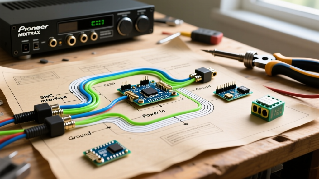

Why a Standard Wiring Diagram Falls Short for MIXTRAX
When upgrading your vehicle's audio system, relying on a generic wiring diagram for a Pioneer MIXTRAX receiver is a recipe for frustration. Pioneer's MIXTRAX technology—featured in popular models like the MVH-S322BT, DEH-S31BT, and AVH-2550NEX—does more than just crossfade tracks. It utilizes an onboard Digital Signal Processor (DSP) to analyze BPM, apply club-style EQ transitions, and sync dynamic visualizers to your dashboard illumination. If your wiring harness is mapped incorrectly, you won't just lose power; you will experience DSP clipping, alternator whine that ruins the audio mix, and visualizer screens that refuse to dim at night.
This installation planning guide goes beyond the basic red-yellow-black power triangle. We will dissect the exact 16-pin harness pinouts, address the notorious 'blue wire trap' that destroys amplifier integration, and outline the precise Steering Wheel Control (SWC) adapter routing required to keep your hands on the wheel without breaking the MIXTRAX continuous playback loop.
The Core 16-Pin Harness: Mapping the MIXTRAX Lifelines
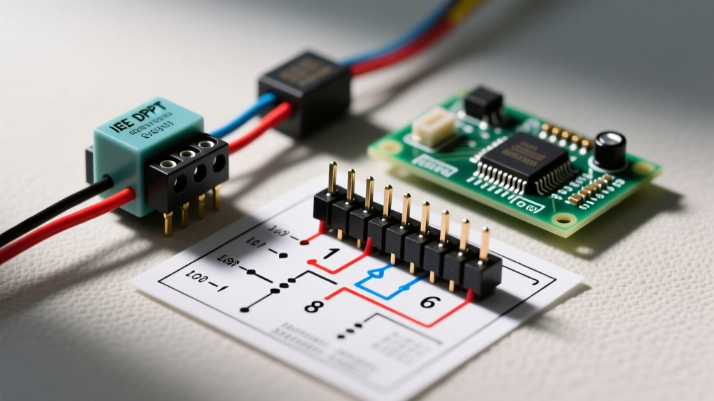
Pioneer utilizes a standardized 16-pin ISO-style connector across almost its entire single-DIN and double-DIN lineup. However, the function of specific wires changes depending on whether you are running a basic speaker setup or a full multi-amplifier MIXTRAX configuration. Below is the critical mapping you need for your installation planning phase.
| Wire Color | Function | MIXTRAX Specific Consideration |
|---|---|---|
| Yellow | 12V Constant (Memory) | Must be connected directly to the battery or a constant 12V fuse. If voltage drops below 11.5V, the MIXTRAX DSP cache will reset, losing your customized EQ presets. |
| Red | 12V Switched (Ignition) | Triggers the boot sequence. Use a T-tap or Add-A-Circuit fuse tap on an ignition-controlled circuit (e.g., windshield wipers or 12V accessory socket). |
| Black | Chassis Ground | Do NOT rely on the factory radio ground. Run a dedicated 12 AWG ground wire to a bare metal chassis point to prevent DSP ground-loop noise. |
| Orange | Illumination / Dimmer | Crucial for MIXTRAX visualizers. This wire tells the screen to switch to 'Night Mode'. If left unconnected, the screen will blind you at night and ruin the club-lighting aesthetic. |
| Blue/White | Amplifier Turn-On | Provides a 200mA remote trigger. Never connect this to high-draw cooling fans or multiple amplifiers without a 30A automotive relay. |
| Purple/Green/White/Gray | Speaker Outputs (x8) | For MIXTRAX DSP processing to function optimally, keep these at 4-ohm impedance. Wiring 2-ohm loads directly to the head unit will trigger thermal protection shutdowns. |
The Blue vs. Blue/White Wire Trap (Critical Failure Mode)
The most common catastrophic wiring error in Pioneer installations involves confusing the Solid Blue wire with the Blue/White stripe wire. According to Crutchfield's car stereo wiring guidelines, the Solid Blue wire is strictly the Power Antenna trigger. It only outputs 12V when the AM/FM radio tuner is actively engaged.
Because MIXTRAX is primarily designed to mix digital audio from USB drives, Bluetooth streaming, and Spotify via the Pioneer Smart Sync app, the AM/FM tuner is rarely the active source. If you wire your amplifier's remote turn-on lead to the Solid Blue wire, your amplifiers will violently shut off every time you switch from the radio to a Bluetooth MIXTRAX session. This causes massive voltage spikes that can blow your amplifier's internal fuses and corrupt the head unit's audio output IC. Always use the Blue/White wire for amplifier remote turn-on, as it outputs a constant 12V signal regardless of the active audio source.
Steering Wheel Control (SWC) Adapters: Keeping the Mix Alive
MIXTRAX thrives on continuous playback, but you still need to skip tracks or adjust volume safely. Factory steering wheel controls operate on a resistive ladder network or a CAN-bus data stream, neither of which the Pioneer head unit can read natively. You must plan for an SWC interface module during your parts procurement phase.
- PAC RP4-PR11 (approx. $65): The industry standard for Pioneer radios. It retains the factory amplified antenna turn-on and maps steering wheel buttons directly to the Pioneer's 3.5mm SWC input jack.
- Axxess ASWC-1 (approx. $75): A universal alternative that auto-detects the vehicle's data bus. Requires splicing into the vehicle's CAN-High and CAN-Low wires, which demands a digital multimeter for verification before soldering.
Expert Tip: When wiring the 3.5mm SWC jack to the Pioneer harness, ensure you use heat-shrink butt connectors (like the 3M Scotchlok series) rather than twist-and-tape methods. The vibration from subwoofers will easily shake loose twisted SWC data wires, causing 'ghost inputs' where the radio randomly skips tracks or changes volume on its own.
RCA Routing and Grounding for DSP Audio Clarity
MIXTRAX applies heavy digital EQ and compression to create seamless transitions. If your RCA signal cables are routed poorly, the DSP will amplify the alternator whine introduced by the vehicle's charging system. To maintain a high Signal-to-Noise Ratio (SNR):
- Separation is Key: Route your RCA cables (e.g., Kicker KICKBLUE 17ft) down the passenger side of the vehicle, while running the 12V power wire for your amplifiers down the driver's side. Maintain at least 18 inches of separation where they must cross.
- Star Grounding: If you are running a multi-amp setup to power the front stage and subwoofers, sand down a single, central chassis point and bolt all amplifier grounds to that exact same location. Grounding amps to different seatbelts or strut towers creates a voltage potential difference, resulting in a high-pitch whine that pierces through the MIXTRAX bass drops.
Step-by-Step Installation Planning Flow
Before you strip a single wire, follow this planning sequence endorsed by MECP (Mobile Electronics Certified Professional) standards:
- Disconnect the Battery: Always drop the negative terminal. Pioneer head units are highly sensitive to voltage spikes during live-wiring, which can fry the internal MOSFET amplifier.
- Identify the Vehicle Harness: Purchase the correct Metra or Scosche T-Harness for your specific make/model/year. This prevents you from cutting factory wires, preserving the vehicle's resale value and CAN-bus integrity.
- Bench-Test the Harness: Before mounting the radio in the dash, connect the Pioneer 16-pin to your T-Harness on a workbench. Power it up with a 12V bench supply to verify MIXTRAX boots, the illumination dimmer triggers, and the SWC adapter learns the steering wheel buttons.
- Solder and Heat-Shrink: Make all permanent connections using a temperature-controlled soldering iron (set to 350°C for 18 AWG wire) and marine-grade adhesive heat shrink.
- Secure the Loom: Wrap the entire harness in Tesa cloth automotive tape to prevent plastic-on-plastic rattling behind the dash fascia when heavy bass hits.
Expert Troubleshooting Edge Cases
The 'Dimmer Stuck' Edge Case: On some modern vehicles (2018+), the factory illumination wire outputs a PWM (Pulse Width Modulation) signal rather than a steady 12V. If you connect a PWM wire to the Pioneer's Orange illumination wire, the MIXTRAX screen will strobe or fail to enter night mode. The fix is to install a 12V automotive relay, using the factory PWM wire to trigger the relay coil, and feeding the Pioneer a clean 12V from the accessory circuit through the relay's normally-open contact.
By treating the wiring diagram for a Pioneer MIXTRAX receiver not just as a power map, but as a blueprint for data, DSP grounding, and illumination logic, you guarantee a professional-grade installation. Proper planning ensures that when the beat drops and the visualizers sync to your dash, the only thing you hear is the music—exactly as the engineers at Pioneer intended.