
Mastering the Septic Tank Electrical Wiring Diagram: An Installation Planning Guide
Designing a reliable wastewater management system requires far more than excavating a site and setting a concrete tank. The electrical infrastructure serves as the central nervous system for any pumped effluent system, grinder pump setup, or Aerobic Treatment Unit (ATU). A poorly executed septic tank electrical wiring diagram does not merely risk a tripped breaker; it can result in catastrophic sewage backups, burnt-out motor windings, and severe National Electrical Code (NEC) violations. According to the Environmental Protection Agency (EPA), precise installation and routine maintenance of septic components are non-negotiable for preventing groundwater contamination and avoiding systemic failure.
This 2026 installation planning guide provides licensed electricians, advanced DIYers, and site contractors with the exact specifications, load calculations, and code-compliant wiring strategies required to deploy a fail-safe septic electrical system.
Core Components of the Septic Electrical Ecosystem
Before drafting your schematic, you must identify the exact hardware profile. A standard pumped septic system relies on four primary electrical nodes:
- Effluent or Grinder Pump: Typically a 1/2 HP to 1 HP submersible motor (e.g., Zoeller M53 Mighty-mate or Myers M53). These draw between 9.4 and 14 amps on a 120V circuit, or roughly 6 to 8 amps on a 240V circuit.
- Control Panel (NEMA 4X): A weatherproof, UV-resistant enclosure housing the motor contactor, overload relays, and terminal blocks. NEMA 4X is mandatory to withstand corrosive septic gases and outdoor weather.
- Float Switches: Liquid level sensors that dictate pump operation. Modern installations utilize 24VAC low-voltage floats (like the SJE Rhombus VerticalMaster) to eliminate 120V shock hazards inside the wet well.
- High-Water Alarm: A dedicated circuit featuring an audible horn and visual strobe (e.g., SJ Electro SJE SignalMaster II) that triggers if the pump fails or the inflow exceeds the pump's discharge rate.
Decoding the Septic Tank Electrical Wiring Diagram
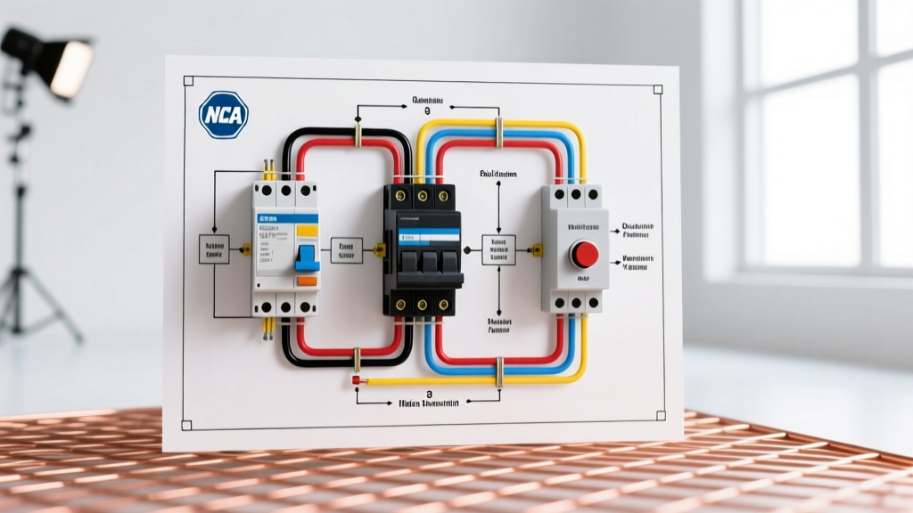
A professional septic wiring diagram is split into two distinct circuits: the Line/Load Circuit (high voltage) and the Control Circuit (low voltage). Mixing these or failing to isolate them is the most common cause of control board fry-outs.
The Line and Load Side (120V/240V)
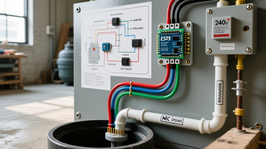
Power originates from the main service panel via a dedicated 20A or 30A breaker. It feeds into the top lugs of the NEMA 4X control box. From the contactor's load side, a 3-wire or 4-wire cable (Hot, Neutral, Ground / Hot, Hot, Ground) runs directly to the submersible pump. Expert Rule: Never use a standard receptacle for a hardwired septic pump. The vibration and moisture will degrade the plug connection, leading to arcing and failure.
The Control Side (24VAC)
To comply with modern safety standards and prevent lethal shocks in the wet well, a 120V-to-24VAC step-down transformer is mounted inside the control panel. The 24V line runs out to the tank, feeding a series of normally-open (pump-up) and normally-closed (pump-down) float switches. When the water rises, the 'pump-on' float closes the 24V circuit, energizing the 120V coil on the main contactor, which subsequently engages the pump motor.
Load Calculations and Wire Sizing Matrix
Voltage drop is the silent killer of submersible septic pumps. If the voltage at the pump terminals drops below 90% of the nameplate rating during startup (Locked Rotor Amps), the motor's start capacitor will overheat and fail within months. The National Fire Protection Association (NFPA) outlines strict voltage drop limitations in NEC Article 430. Below is the 2026 standard sizing matrix for THWN-2 copper conductors in PVC conduit, maintaining a maximum 3% voltage drop.
| Pump Horsepower | Voltage | Full Load Amps (FLA) | Max Distance (12 AWG) | Max Distance (10 AWG) | Max Distance (8 AWG) |
|---|---|---|---|---|---|
| 1/2 HP | 115V | 9.8 A | 45 ft | 110 ft | 180 ft |
| 3/4 HP | 115V | 13.8 A | 30 ft | 75 ft | 125 ft |
| 1 HP | 230V | 8.0 A | 140 ft | 280 ft | 450 ft |
| 1.5 HP | 230V | 10.0 A | 110 ft | 220 ft | 360 ft |
Note: Always calculate distance based on the total wire run (panel to tank), not just the trench length. Factor in vertical drops into the tank and panel routing.
NEC Trenching, Conduit, and Wet Location Rules
The physical routing of your wiring is governed by NEC Table 300.5. In 2026, local inspectors are heavily scrutinizing septic trenching due to soil shifting and root intrusion.
- Direct Burial vs. Conduit: While UF-B (Underground Feeder) cable can be direct-buried at a minimum depth of 24 inches, industry best practice mandates using Schedule 40 PVC conduit for horizontal runs and Schedule 80 PVC where the conduit emerges from the ground (subject to physical damage).
- Pulling THWN-2: Pulling individual THWN-2 conductors through a 1-inch PVC conduit allows for future upgrades and provides superior moisture protection compared to UF-B jackets, which are prone to micro-tearing from sharp aggregate in backfill.
- Warning Tape: Lay bright red or yellow 'Caution: Buried Electric Line' detectable tape exactly 12 inches above the conduit before backfilling. This costs roughly $15 per roll and prevents future landscaping disasters.
Contractor Insight: As of 2026, expect to pay between $18 and $25 per linear foot for professional trenching and conduit laying, depending on soil composition and local labor rates. Always rent a walk-behind trencher with a rock blade if your site features heavy clay or shale.
The GFCI Dilemma: Nuisance Trips vs. Code Compliance
One of the most hotly debated aspects of septic electrical planning is Ground Fault Circuit Interrupter (GFCI) protection. NEC Article 210.8(F) requires GFCI protection for 125V, single-phase, 15A and 20A receptacles in damp/wet locations, which often encompasses sump and septic pumps.
The Edge Case: Submersible motors generate significant inductive inrush currents and minor, harmless leakage to ground during startup. Standard residential GFCI breakers frequently interpret this as a ground fault, resulting in 'nuisance tripping.' A tripped septic pump means a flooded yard and a $5,000 environmental cleanup bill.
The Solution: Do not use standard receptacles. Hardwire the pump directly to the panel. If your local jurisdiction strictly interprets the code to require GFCI protection for hardwired septic motors, install a specialized motor-rated GFCI breaker (such as the Eaton CHFGFI series) designed with a higher trip threshold to tolerate motor inductance, paired with a high-water alarm to notify the homeowner if the breaker does trip.
5-Step Installation Planning Workflow
Follow this sequential workflow to ensure a smooth inspection and long-term reliability:
- Site Assessment & Load Profiling: Determine the total dynamic head (TDH) of the pump to select the correct HP. Map the exact wire run distance to calculate voltage drop.
- Panel Placement Strategy: Mount the NEMA 4X control panel on a 4x4 pressure-treated post or the side of a structure, at least 5 feet above grade, ensuring it is accessible but out of reach of children and landscaping equipment.
- Conduit & Trenching Execution: Dig to 18-24 inches. Lay PVC, glue joints with medium-body clear cement, and pull a nylon pull-string alongside your THWN-2 wires for future use.
- Float Calibration: Before sealing the tank lid, manually lift the floats to verify the sequence: Pump-Off (lowest), Pump-On (middle), Alarm (highest). Secure float tethers to the discharge pipe using stainless steel hose clamps to prevent tangling.
- Megohmmeter Testing: Before energizing, use a megohmmeter (Megger) to test the insulation resistance of the pump cable. A reading below 2 Megohms indicates a compromised cable jacket that will fail once submerged.
Common Edge Cases and Failure Modes
Even with a perfect schematic, environmental factors can destroy a system. Watch out for these specific failure modes:
- Hydrogen Sulfide Corrosion: Septic tanks generate H2S gas, which turns into sulfuric acid when it meets condensation. This acid eats standard brass and copper terminal blocks. Fix: Use nickel-plated or tin-plated terminal blocks inside the control panel and apply dielectric grease to all tank-side wire nuts.
- UV Degradation of UF-B: If UF-B cable is used and left exposed to sunlight for more than a few weeks before burial, the gray PVC jacket becomes brittle and cracks. Always transition to THWN-2 in conduit if the wire will be exposed.
- Float Switch Tether Tangling: In turbulent tanks, wide-angle floats can wrap around the discharge pipe or pump power cord. Fix: Use narrow-angle vertical floats (like the SJE Rhombus VerticalMaster) which require only 2.5 inches of clearance and cannot tangle.
Final Thoughts on System Longevity
A meticulously planned septic tank electrical wiring diagram bridges the gap between a system that fails in three years and one that runs flawlessly for two decades. By prioritizing low-voltage control circuits, calculating exact voltage drops, and respecting NEC wet-location mandates, you ensure both environmental safety and operational reliability. For further regional specifications and advanced wastewater treatment schematics, consult the resources available at the National Environmental Services Center (NESC).