
Decoding the Club Car DS Electrical Architecture
When tackling a wiring diagram for Club Car DS golf carts, the first critical step is identifying your specific electrical generation. The Club Car DS platform, produced from 1981 through 2014, underwent several massive electrical overhauls. Misidentifying your system is the leading cause of fried controllers—a mistake that will cost you between $450 and $800 in replacement parts in 2026. Broadly, DS carts fall into three categories: 36V Series (1981-1995), 48V Series (1996-2001), and the 48V IQ system (2001-2014).
The older Series models rely on a simple series-wound motor and a mechanical V-glide or early Forward/Reverse (F&R) switch to manage speed via resistor coils or early solid-state controllers. The IQ system introduced a separately excited (SEPEX/ADC) motor, a sophisticated Curtis 1268 controller, and a solid-state V-Glide replacement. Understanding this distinction dictates entirely different wiring pathways for the motor terminals and solenoid activation.
| System Type | Voltage | Motor Type | Controller Model | Typical 2026 Replacement Cost |
|---|---|---|---|---|
| Series (Pre-96) | 36V | Series Wound | Curtis 1204 / V-Glide | $350 - $450 |
| Series (96-01) | 48V | Series Wound | Curtis 1204 | $400 - $500 |
| IQ (01-14) | 48V | ADC (SEPEX) | Curtis 1268 | $550 - $750 |
Essential Tools and Wire Gauge Specifications
Before cutting or crimping a single wire, you must adhere to proper ampacity standards. Golf cart powertrains draw massive transient currents—often exceeding 300 amps during heavy acceleration or hill climbs. According to the National Electrical Code (NEC) guidelines for mobile DC applications, undersized wiring leads to severe voltage drop, melted insulation, and potential fire hazards.
- Main Power Loop (Battery to Solenoid, Solenoid to Controller): Use 2 AWG high-strand-count welding cable. Do not use standard THHN copper wire; it lacks the flexibility required for vehicular vibration and will snap internally over time.
- Motor Terminals: 2 AWG or 4 AWG flexible battery cable, depending on the specific motor upgrade (e.g., if you have installed a high-torque D&D Motor).
- Control Circuit (Solenoid Coil, Ignition, F&R Microswitches): 14 AWG or 12 AWG stranded automotive primary wire.
- Tools: Hydraulic wire crimper (for 2 AWG lugs), heat shrink tubing (3/8-inch and 1/2-inch), and a digital multimeter capable of measuring DC voltage and resistance.
Step-by-Step Walkthrough: Powertrain Wiring
This walkthrough focuses on the most common DIY repair and upgrade scenario: wiring a 48V IQ system with a Curtis 1268 controller and an ADC motor. If you are wiring a 36V Series cart, the solenoid and battery loop steps apply, but the motor terminal mapping will differ.
Step 1: The Main Solenoid and Battery Loop
The main solenoid acts as the high-current gatekeeper. For 48V systems, this is typically a heavy-duty 400A continuous-duty solenoid (such as an Albright SW200 equivalent).
- Run a 2 AWG red cable from the main positive battery pack terminal to the large input stud on the solenoid.
- Run a 2 AWG black cable from the main negative battery pack terminal directly to the controller's B- (Battery Negative) terminal.
- Connect a 2 AWG red cable from the solenoid's large output stud to the controller's B+ (Battery Positive) terminal.
Critical Warning: Never route the main negative battery cable through the solenoid. The solenoid should only switch the positive high-current leg. Switching the negative leg on a Club Car DS can cause catastrophic controller failure due to voltage spike feedback.
Step 2: Controller Integration and Pre-Charge Circuit
When the solenoid engages, it dumps 48V directly into the controller's main capacitors. Without a pre-charge resistor, this inrush current will weld the solenoid contacts shut and blow the controller's internal diodes.
- Locate the pre-charge resistor (typically a 470-ohm, 5-watt ceramic resistor) on the solenoid.
- Wire one end of the resistor to the solenoid's input stud (Battery side) and the other end to the output stud (Controller side).
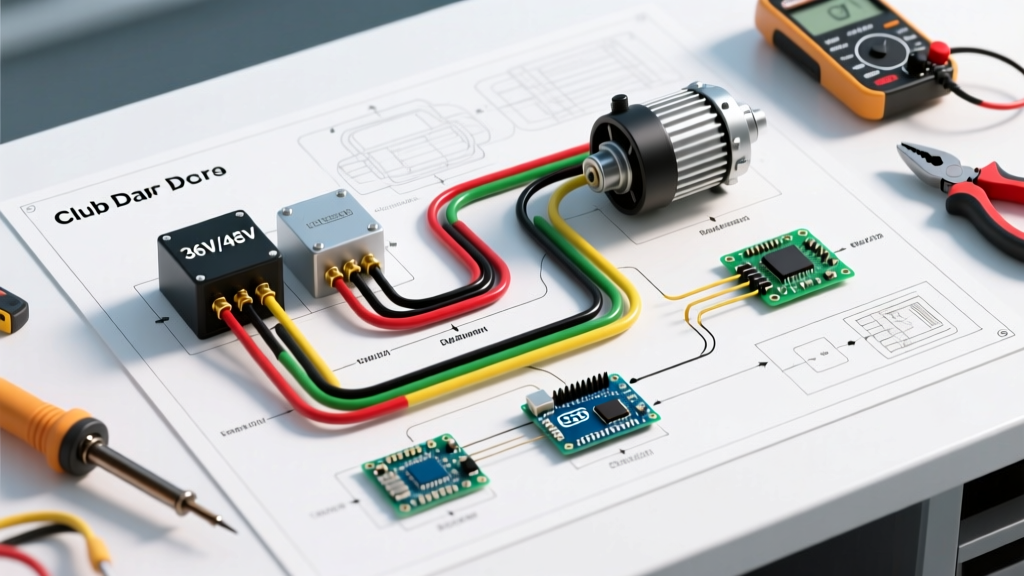
- Verify the controller's M- (Motor Negative) terminal is connected to the motor's A2 terminal using a 2 AWG cable.
Step 3: Motor Terminal Mapping (A1, A2, S1, S2)
This is where 90% of DIY wiring mistakes occur. The Club Car DS ADC motor features four terminals: A1, A2, S1, and S2. The Curtis 1268 controller requires a very specific mapping to manage both the armature and the stator fields for regenerative braking and speed control.
- Motor A1: Connects to the Controller A1 terminal. (Carries main armature current).
- Motor A2: Connects to the Controller M- terminal. (Completes the armature circuit).
- Motor S1: Connects to the Controller S1 terminal. (Stator field positive).
- Motor S2: Connects to the Controller S2 terminal. (Stator field negative).
Note for Series Motor Upgrades: If you are retrofitting an older Series motor, it also has A1, A2, S1, and S2 terminals, but they are wired entirely differently. On a Series motor, A2 and S2 must be physically isolated from the motor casing and from each other. Connecting them together will result in an immediate dead short and a blown controller.
Wiring the Forward and Reverse (F&R) Microswitches
The Club Car DS utilizes a mechanical F&R switch located under the seat or behind the dash, which houses two microswitches. These microswitches do not carry the main motor current; they only carry the low-current signal (typically 48V at less than 2 amps) to trigger the solenoid coil and tell the controller which direction to spin the motor.
- Identify the two microswitches on the F&R assembly. One is for Forward, one is for Reverse.
- Wire the common terminal of both microswitches to a switched 48V positive source (usually the key switch output).
- The Forward microswitch's normally open (NO) terminal routes to the controller's FWD input pin.
- The Reverse microswitch's NO terminal routes to the controller's REV input pin and simultaneously routes to the solenoid's small activation coil terminal.
Always refer to the official Club Car owner and technical manuals for your specific year's pinout, as the IQ harness uses a 16-pin Molex connector where pin locations dictate directional logic.
Real-World Troubleshooting and Failure Modes
Even with a perfect wiring diagram, environmental factors and component wear can introduce faults. Here is how to diagnose the most common Club Car DS electrical failures using a multimeter.
The Solenoid Click Test
Turn the key on and press the accelerator. You should hear a distinct, loud 'click' from the solenoid. If it clicks but the cart does not move:
- Test for Voltage Drop: Set your multimeter to DC Volts. Place the red probe on the solenoid's input stud and the black probe on the output stud. Press the accelerator. A reading above 0.5V indicates the solenoid's internal copper contacts are pitted or carbon-fouled. Replace the solenoid.
- Check the Pre-Charge Resistor: If the resistor is burnt open, the controller will lock out and prevent the cart from driving to protect itself from inrush current spikes.
Motor Field Wiring Shorts
If your cart trips the main breaker immediately upon pressing the pedal, you likely have a short in the S1 or S2 stator wiring. Because these wires route under the cart, they are highly susceptible to abrasion from debris. Inspect the 2 AWG cables running to S1 and S2 for cracked insulation. For long-term reliability, wrap all undercarriage motor wiring in split-loom tubing and secure it with UV-resistant zip ties, keeping it clear of the rear axle and brake drums.
Working with 48V DC systems presents serious arc-flash and shock hazards. Always disconnect the main negative battery cable first and isolate it with a non-conductive boot before beginning any wiring work, in compliance with standard OSHA electrical safety practices. By following this precise wiring diagram for Club Car DS models, you ensure a reliable, high-torque powertrain capable of handling the demands of modern golf cart usage.