
Decoding the Wiring Diagram for EZGO Golf Cart Systems
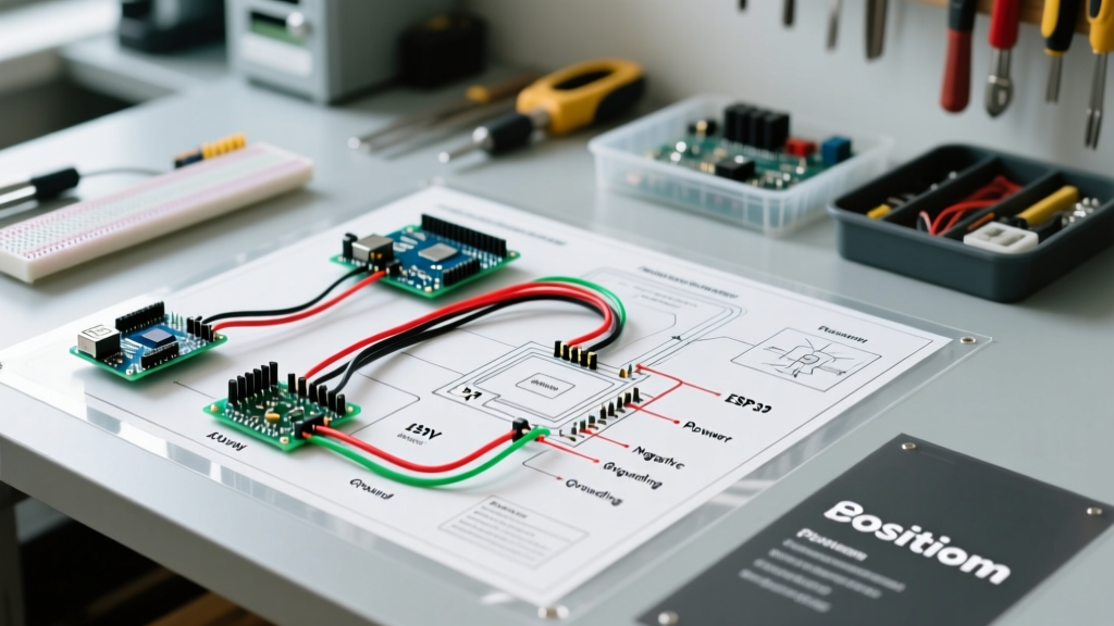
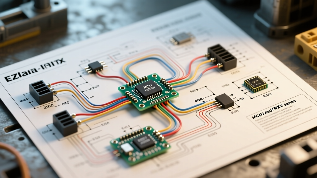
Understanding the correct wiring diagram for EZGO golf cart models is the difference between a seamless restoration and a catastrophic electrical fire. EZGO has dominated the personal and fleet electric vehicle market for decades, but their electrical architectures have evolved drastically from the early 36V resistor-based TXT models to the modern 48V and 72V AC-driven RXV platforms. This comprehensive vehicle-specific guide breaks down the exact wiring topologies, component pinouts, and diagnostic workflows required to safely wire, upgrade, or repair your cart.
Before touching a single terminal, always disconnect the main negative battery cable. Golf cart battery banks operate at high amperage (often exceeding 400A under load), and a short circuit across a 48V or 72V pack can instantly weld tools, melt 6 AWG cables, and cause severe arc flash injuries. According to the U.S. Consumer Product Safety Commission (CPSC), improper battery wiring and inadequate overcurrent protection are leading causes of thermal runaway in lead-acid and lithium golf cart systems.
EZGO TXT Series (1975–1994): Resistor-Based Wiring Architecture
The earliest TXT models utilized a 36V system comprising six 6V lead-acid batteries wired in series. Unlike modern carts that use solid-state controllers to manage speed, the Series TXT relied on a mechanical V-Glide and heavy-duty resistor coils to step down voltage to the motor.
Key Components and Routing Logic
- V-Glide (Variable Resistor): Mounted under the driver’s side floorboard, the V-Glide uses a carbon track to vary resistance based on pedal position. The wiring diagram routes the throttle signal through this resistor before reaching the speed control board. Failure Mode: The carbon track wears unevenly, creating dead spots or causing sudden, uncommanded acceleration.
- Forward/Reverse (F/R) Switch: In Series models, the F/R switch physically reverses the polarity of the motor’s field windings relative to the armature. This switch carries the full motor current (up to 150A). The wiring must utilize minimum 4 AWG flexible welding cable to prevent voltage drop and terminal melting.
- Series Motor: Wired with four terminals (A1, A2, S1, S2). A1 and S1 connect to the controller/solenoid, while A2 and S2 connect to the F/R switch. Reversing the S1/S2 relationship to A1/A2 dictates direction.
EZGO TXT DCS, PDS, and Freedom Systems (1994–2014)
The introduction of the DCS (Drive Control System) and later the PDS (Precision Drive System) revolutionized EZGO wiring. These systems transitioned to 48V (eight 6V batteries) and introduced the Curtis 1206 solid-state motor controller. The wiring diagram for EZGO golf cart PDS models is significantly more complex, utilizing low-voltage logic circuits to command high-voltage power delivery.
Solenoid and Controller Pinouts
The PDS wiring diagram centers around a 4-terminal heavy-duty solenoid and the Curtis 1206 controller. The large terminals handle the main 48V pack voltage (B+) and the motor positive. The small terminals handle the activation coil and the precharge circuit.
Critical Engineering Note: Never bypass the precharge resistor on a PDS or Freedom cart. This 250-ohm, 10W ceramic resistor bleeds pack voltage into the controller’s internal capacitors before the main solenoid contacts close. Bypassing it causes a massive inrush current that will instantly weld the solenoid contacts and destroy the controller’s main MOSFETs.
The F/R switch in PDS models no longer carries high current. Instead, it houses three microswitches that send 48V logic signals to the controller’s J3 or J4 directional pins. The controller then handles the phase reversal internally via solid-state relays.
Modern EZGO RXV (2008–Present): AC and CAN Bus Topologies
The RXV platform abandoned the brushed DC motors of the TXT line in favor of 3-phase AC induction and synchronous motors, paired with Danaher or Delta-Q controllers. The wiring diagram for EZGO golf cart RXV models is defined by its lack of high-current mechanical switches and its reliance on CAN bus communication.
Inductive Throttle Sensor (ITS) and 3-Phase Routing
- ITS Throttle: Unlike the mechanical potentiometers of the past, the RXV uses an Inductive Throttle Sensor. It outputs a clean 0.8V to 4.2V analog signal to the controller. This eliminates the moisture-induced corrosion that plagued older MCOR units.
- 3-Phase Motor Cables: The controller connects to the AC motor via three heavy-gauge (typically 2 AWG) phase wires labeled U, V, and W. Swapping any two of these wires will reverse the motor's direction, a useful diagnostic trick if the cart runs backward after a controller replacement.
- Onboard Charger (OBC) Integration: The RXV wiring diagram integrates the Delta-Q charger directly with the controller via a communication harness. The controller monitors individual cell voltages (especially in 2020+ lithium-ion conversions) and dictates the charge profile to the OBC.
Wire Gauge and Component Specification Matrix
Selecting the correct wire gauge is non-negotiable. Referencing the National Fire Protection Association (NFPA 70) guidelines for DC ampacity and voltage drop, use the following specifications for EZGO restorations and upgrades:
| Circuit / Function | Recommended Wire Gauge (AWG) | Expected Peak Current | Insulation & Terminal Type |
|---|---|---|---|
| Main Battery Pack Interconnects | 2 AWG or 1/0 AWG | 400A - 600A | EPDM Rubber, Heavy-Duty Ring Terminals |
| Solenoid to Controller (B+) | 2 AWG | 300A - 450A | High-Strand Flex Welding Cable |
| Controller to DC Motor (A+/A-) | 4 AWG | 150A - 250A | PVC/High-Strand, Heat Shrink Sealed |
| RXV 3-Phase AC Motor (U, V, W) | 2 AWG | 200A (RMS) | Silicone Insulation (High Temp) |
| 12V Step-Down Converter Input | 10 AWG | 15A - 20A | Standard Automotive GXL, Inline Fuse |
| Logic / Throttle / CAN Bus | 18 AWG to 16 AWG | < 1A | Shielded Multi-Conductor (for CAN) |
Diagnostic Troubleshooting: The 'Click but No Go' Workflow
The most common issue when tracing a wiring diagram for EZGO golf cart systems is the 'solenoid clicks but the cart doesn't move' scenario. Follow this precise multimeter workflow to isolate the fault without replacing expensive parts blindly.
- Verify Pack Voltage: Set your multimeter to DC Volts (200V range). Measure directly across the main battery pack terminals. A fully charged 48V lead-acid pack should read 50.9V. If it reads below 44V under load, the batteries are sulfated or a cell has failed. For deep insights into lead-acid charging and sulfation, consult the Battery University (BU-403) guidelines.
- Test Solenoid Coil Activation: Place the red probe on the solenoid's small activation terminal and the black probe on the cart's main ground. Press the throttle. You should see full pack voltage (e.g., 48V) initially, dropping to ~12V once the economizer circuit inside the controller engages. If you see 0V, the issue is in the ignition switch, tow/run switch, or F/R microswitches.
- Measure High-Side Voltage Drop: With the cart jacked up and wheels off the ground, press the throttle. Place your multimeter probes on the two LARGE terminals of the solenoid. A healthy, closed solenoid will show a voltage drop of less than 0.1V. If you read full pack voltage (e.g., 48V) across the large terminals while the solenoid is clicking, the internal copper contacts are pitted or welded open. Replace the solenoid.
- Check the Precharge Circuit: If the solenoid does not click at all, but you have 48V at the small activation terminal, test the precharge resistor. Disconnect power and measure resistance across the 250-ohm ceramic resistor. If it reads infinite (open), the controller is preventing the main contactor from closing to protect itself from an inrush event.
- Verify Controller Output: If the solenoid closes (0.1V drop across large posts) but the motor doesn't spin, measure the voltage at the motor terminals (A1 and A2 for DC). If the controller is receiving throttle input but outputting 0V to the motor, the internal MOSFET bridge has failed, requiring a controller rebuild or replacement.
Safety, Codes, and Final Wiring Best Practices
When executing any wiring diagram for EZGO golf cart projects, always use adhesive-lined marine-grade heat shrink on all crimped terminals. The under-seat environment of a golf cart is highly corrosive due to hydrogen sulfide gas off-gassing from lead-acid batteries during the absorption charging phase. Standard vinyl electrical tape will degrade within months, leading to stray voltage, chassis grounding, and accelerated frame corrosion.
Furthermore, if you are upgrading a vintage TXT to a modern 48V lithium-ion battery pack, you must install a high-amperage Class T fuse (minimum 400A for DC applications) within 18 inches of the main positive battery terminal. This complies with modern ABYC and NFPA standards for DC overcurrent protection and prevents catastrophic cable fires in the event of a dead short. Always map your physical wiring against the factory schematic, verify continuity before applying power, and never bypass factory safety interlocks like the tow/run switch or the seat safety microswitch.