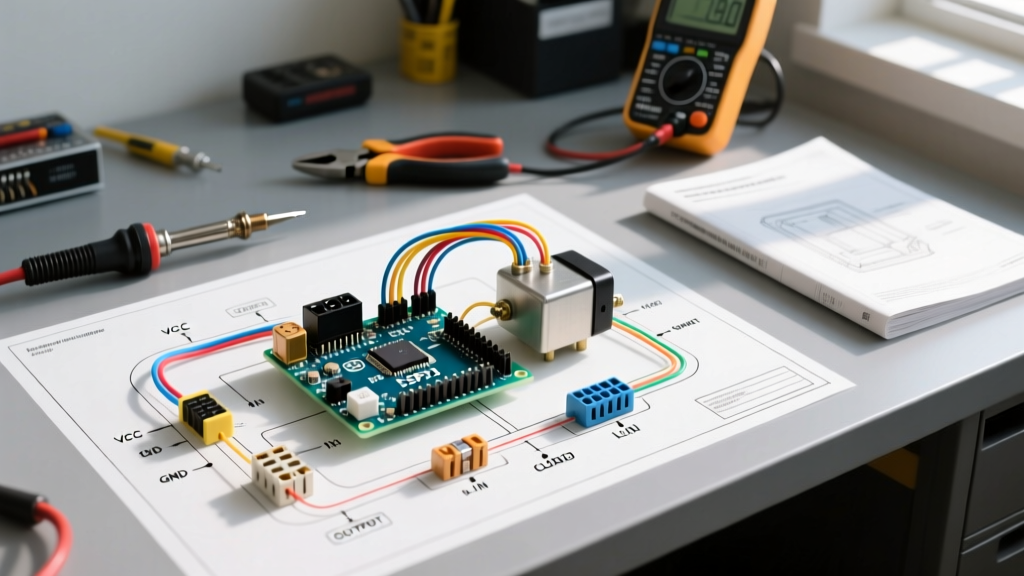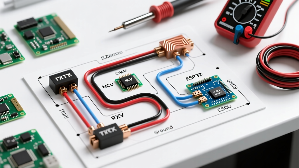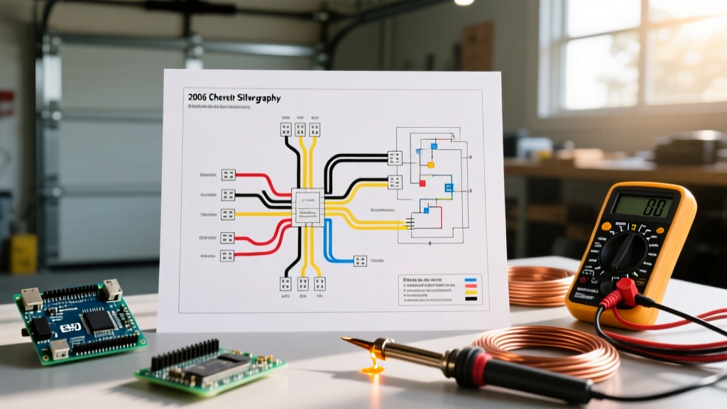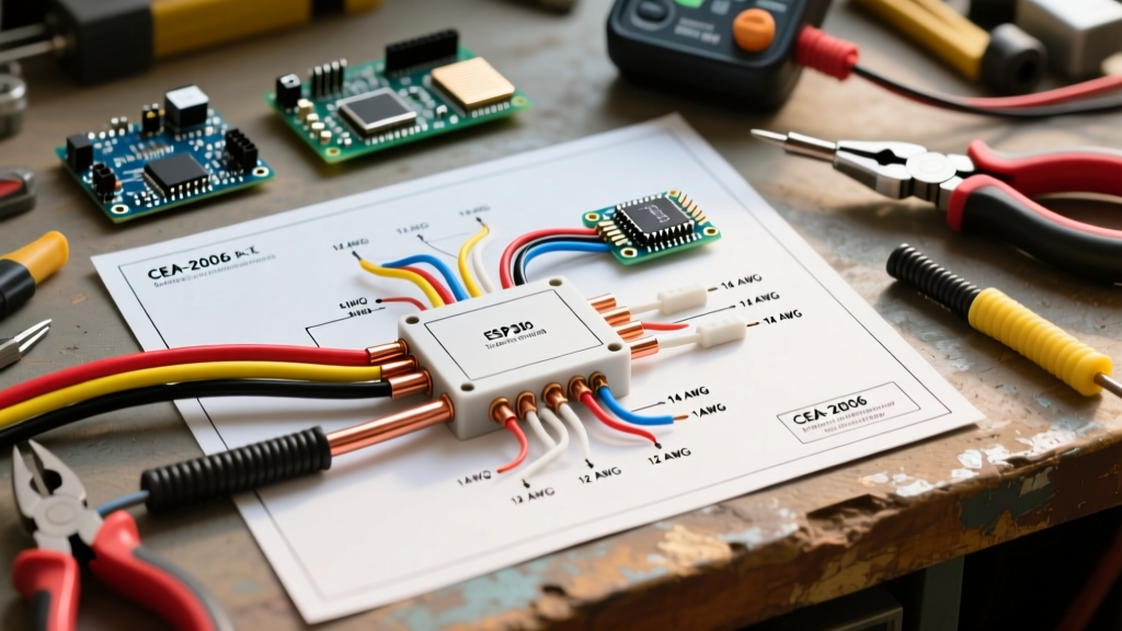

The Core Architecture: Decoding the 5-Pin ISO Mini Relay
When upgrading automotive, marine, or off-road lighting systems, relying on factory headlight switches to carry high-amperage loads is a recipe for melted harnesses and voltage drop. The solution lies in understanding and executing a precise 5 pin relay wiring diagram for lights. Unlike standard 4-pin relays, the 5-pin ISO mini relay (often referred to as a Bosch-style relay) introduces a Normally Closed (NC) contact, unlocking advanced logic capabilities like Daytime Running Light (DRL) cutouts and dual-circuit switching.
Before cutting a single wire, installation planning requires a firm grasp of the internal Single Pole Double Throw (SPDT) architecture. According to MAD Electrical's Automotive Relay Guide, misidentifying the coil pins from the load pins is the most common cause of immediate harness failure.
Standard ISO Mini Relay Pinout Matrix
| Pin Number | Terminal Type | Function | Recommended Wire Gauge (12V) |
|---|---|---|---|
| 30 | Common (COM) | Main 12V+ Power Input from Battery | 12 AWG or 14 AWG |
| 85 | Coil (-) | Ground for the Electromagnet Coil | 16 AWG or 18 AWG |
| 86 | Coil (+) | 12V+ Trigger Signal (from switch/ECU) | 16 AWG or 18 AWG |
| 87 | Normally Open (NO) | Power Output to Lights (Active when triggered) | 12 AWG or 14 AWG |
| 87a | Normally Closed (NC) | Power Output (Active when relay is OFF) | 14 AWG (if utilized) |
Pre-Installation Load & Wire Gauge Planning Matrix
A robust 5 pin relay wiring diagram for lights is only as reliable as the wire gauge and overcurrent protection supporting it. Automotive environments are harsh; engine bay temperatures can exceed 125°C (257°F), which severely degrades the current-carrying capacity of standard PVC wire. For this reason, planning must account for continuous vs. intermittent loads and thermal derating.
The following matrix provides exact specifications for common lighting upgrades. Note that fuses are sized to protect the wire, not the load. Always follow the 80% continuous load rule for lighting circuits that remain on for more than 15 minutes.
| Total Lighting Load | Max Continuous Amps | Wire Gauge (GXL/SXL) | Inline Fuse Rating | Typical Application |
|---|---|---|---|---|
| Up to 120W | 10A | 16 AWG | 15A ATO/ATC | LED Light Pods (Pair) |
| Up to 240W | 20A | 14 AWG | 20A ATO/ATC | Halogen H4 Headlights |
| Up to 360W | 30A | 12 AWG | 25A or 30A ATO/ATC | 50-inch LED Light Bar |
Step-by-Step Execution Plan
With your components procured and load calculated, proceed with the physical routing. Professional installers divide the 5 pin relay wiring diagram for lights into three isolated stages to prevent cross-contamination of high-current and low-current signal wires.
Stage 1: High-Current Power Routing (Pins 30 & 87)
- Battery Connection: Run your primary 12 AWG or 14 AWG GXL wire from the positive battery terminal. Install a weather-sealed inline fuse holder (e.g., Littelfuse FHAC series) within 6 inches of the battery post. This is non-negotiable; an unfused wire near the battery is a direct fire hazard.
- Relay Input (Pin 30): Terminate the fused wire into Pin 30 of the relay socket using a Delphi Metri-Pack 280 series female terminal.
- Load Output (Pin 87): Run a wire of the same gauge from Pin 87 directly to the positive terminal of your lighting fixture. Ensure the ground wire for the light itself is of equal gauge and secured to bare, unpainted chassis metal using a ring terminal and star washer.
Stage 2: Coil Control & Grounding (Pins 85 & 86)
The coil circuit draws minimal current (typically 150mA to 200mA), allowing the use of 18 AWG wire. However, voltage drop remains a critical failure point.
- Pin 85 (Ground): Route an 18 AWG black wire from Pin 85 to a verified chassis ground. Do not daisy-chain this ground with the lighting fixture's ground.
- Pin 86 (Trigger): Connect an 18 AWG red wire from Pin 86 to your trigger source. This could be a toggle switch fed by an ignition-switched fuse, or a direct tap into the factory headlight positive wire using a T-tap or Posi-Tap connector.
Stage 3: Leveraging the Normally Closed Pin (87a)
The defining feature of the 5 pin relay is Pin 87a. When the relay coil is de-energized, Pin 30 is internally connected to Pin 87a. This is heavily utilized in DRL cutout wiring diagrams. For example, if you wire your DRLs to Pin 87a and your main headlights to Pin 87, turning on the headlights energizes the coil, instantly cutting power to the DRLs while illuminating the headlights. If your installation does not require this logic, simply leave Pin 87a empty and insulate the cavity to prevent moisture ingress.
Critical Edge Cases & Failure Modes
Even with a perfect diagram, real-world variables can compromise the system. As highlighted in Littelfuse Automotive Relay Application Notes, ignoring electromagnetic and thermal edge cases leads to premature component death.
The Back-EMF Threat to Modern ECUs
When the trigger signal to Pin 86 is removed, the collapsing magnetic field inside the relay coil generates a massive reverse voltage spike (Back-Electromotive Force), sometimes exceeding 100V. If your trigger source is a modern vehicle's Body Control Module (BCM) or ECU rather than a simple mechanical switch, this spike will fry the solid-state driver inside the computer.
Expert Fix: Always use a relay with an internal suppression resistor/diode (like the Bosch 0332014150) when tapping into ECU-level signals. If using a standard relay, solder a 1N4001 flyback diode across the coil wires (Pin 85 and 86), with the diode's cathode (stripe) facing the 12V+ trigger source.
Coil Chattering from Voltage Drop
If the 18 AWG trigger wire running to Pin 86 is excessively long (over 15 feet) or passes through high-resistance connectors, the voltage reaching the coil may drop below 9V. This places the relay in a linear, semi-engaged state. The contacts will rapidly open and close ("chatter"), causing severe arcing at Pin 87, melting the plastic socket, and visibly flickering your lights. Always measure voltage at Pin 86 with the trigger active; it must read above 11.5V under load.
2026 Component Procurement Guide
Sourcing high-quality components prevents the "ghost gremlins" associated with cheap, unbranded relays. Based on current market availability and industry reliability standards, here is the recommended bill of materials for a professional-grade installation:
- The Relay: Omron G8JN-1C7T-R-DC12 (Approx. $4.50 - $6.00). Features a built-in resistor for coil suppression and handles 35A make currents. Alternatively, the Bosch 0332014150 (Approx. $7.00) is the gold standard for heavy-duty continuous cycling.
- The Wire: SAE J1128 GXL or SXL cross-linked polyethylene wire (Approx. $0.45/ft). As noted by Mouser's Automotive Applications Guide, cross-linked insulation resists under-hood heat and abrasion far better than standard PVC (THHN) wire.
- The Socket: Delphi Metri-Pack 280 series pigtail with 12-inch 14 AWG leads. Avoid the cheap $2 generic sockets with thin 18 AWG leads on the power pins; they will bottleneck your current and melt under a 25A continuous load.
- Terminals & Sealing: Adhesive-lined heat shrink (e.g., 3M EPS300) for all inline splices to prevent capillary action from drawing moisture into the copper strands.
Final Pre-Flight Checklist
Before applying power for the first time, verify the following:
- Is the main fuse removed from the battery line?
- Are all ground points sanded to bare metal and treated with dielectric grease?
- Is the flyback diode installed (if triggering via a solid-state ECU module)?
- Is Pin 87a properly insulated if left unused?
By treating the 5 pin relay wiring diagram for lights not just as a schematic, but as a comprehensive installation plan, you ensure a lighting system that delivers maximum lumen output, zero voltage drop, and absolute fire safety for the life of the vehicle.