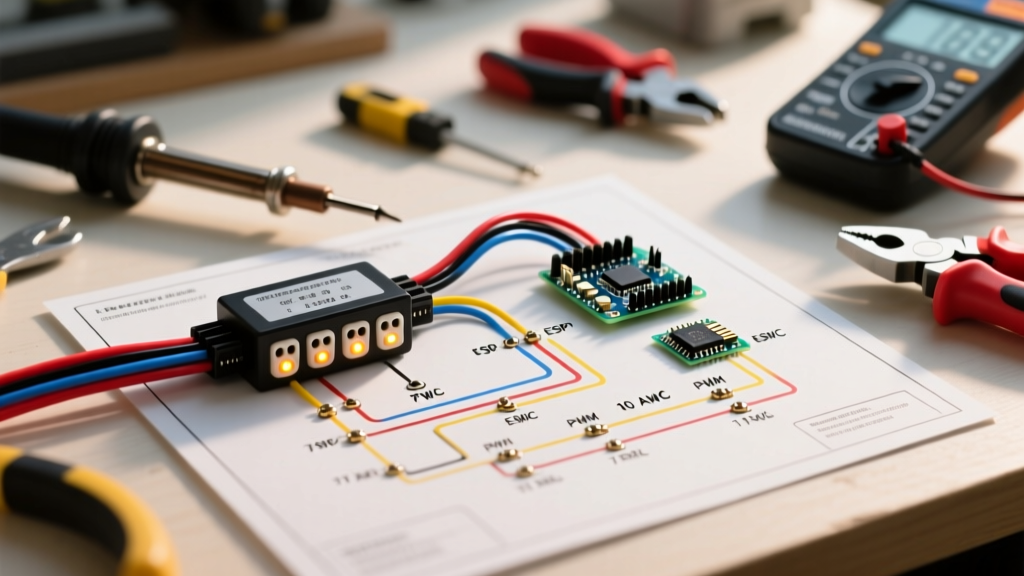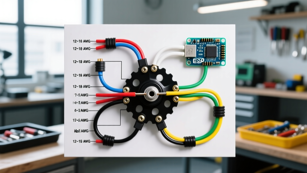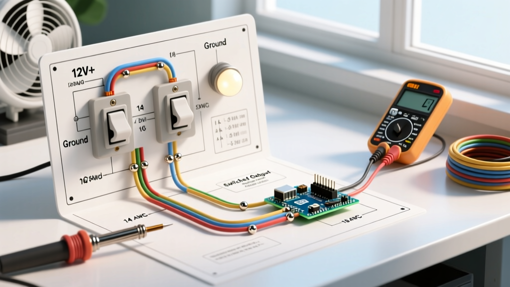

Introduction to 12V DC Dual-Control Circuits in RVs
When outfitting a camper van, skoolie, or overland RV, managing your 12V DC house loads efficiently is critical. One of the most common and practical setups in modern van builds is pairing a high-ventilation roof fan (like the MaxxAir Deluxe) with an interior LED lighting circuit, both controlled from a single, centralized location. This guide provides a comprehensive, vehicle-specific wiring diagram for double switch for fan and light configurations, tailored specifically for 12V DC mobile environments.
Unlike residential 120V AC wiring, 12V DC systems require strict adherence to voltage drop calculations, proper overcurrent protection, and marine-grade vibration resistance. According to guidelines adapted from the NFPA 70 (National Electrical Code) Article 551 for recreational vehicles, all DC circuits must be protected by fuses or circuit breakers located as close to the power source as possible. Furthermore, mobile environments demand tinned copper wire and heat-shrink crimp terminals to prevent corrosion and connection failure due to chassis vibration.
Expert Safety Callout: Before beginning any 12V DC wiring in your vehicle, always disconnect the negative terminal of your house battery bank. Verify zero voltage at your busbars using a digital multimeter before stripping or crimping any wires.
Core Component BOM & 2026 Pricing Guide
To ensure longevity and safety in a mobile environment, we recommend marine-grade components. Standard automotive parts often fail prematurely in high-humidity RV environments (like near a roof fan or shower). Below is the recommended Bill of Materials (BOM) for this specific dual-switch circuit, reflecting early 2026 market pricing.
| Component | Recommended Model / Spec | Est. 2026 Cost | Purpose |
|---|---|---|---|
| Double Rocker Switch | Nilight 2-Gang Aluminum Panel (90005B) or Blue Sea WeatherDeck | $16.00 - $45.00 | User interface for Fan and Light |
| Fuse Block | Blue Sea Systems ST Blade 6-Circuit (5025) | $28.50 | Centralized overcurrent protection |
| Primary Wire | Ancor 14 AWG Marine Tinned Copper (Duplex) | $32.00 / 50ft | Primary power and ground routing |
| Fuses | Littelfuse ATO 10A (Fan) & 3A (Light) | $4.50 / pair | Circuit protection |
| Terminals | 3M Heat-Shrink 1/4" Female Disconnects | $12.00 / pack | Vibration-proof switch connections |
Understanding the Double Rocker Switch Pinout
Most standard 12V marine and RV rocker switches (including Carling Technologies and Nilight variants) utilize a 3-pin layout per gang (switch). Understanding this pinout is the foundation of our wiring diagram for double switch for fan and light setups.
- Pin 1 (Ground / Illumination): Connects to the negative busbar. This completes the circuit for the switch's internal LED indicator light.
- Pin 2 (Power IN): Connects to the 12V+ positive source (via the fuse block). This is the hot feed.
- Pin 3 (Power OUT / Load): Connects to the positive wire of your appliance (Fan or Light).
When the switch is flipped to the "ON" position, internal contacts bridge Pin 2 and Pin 3, sending 12V to the load, while simultaneously grounding Pin 1 to illuminate the switch bezel.
Step-by-Step Wiring Execution
Phase 1: Power Source to Fuse Block
Run a heavy-gauge wire (typically 6 AWG or 4 AWG, depending on your total inverter and house load calculations) from your positive battery terminal to a main Class T fuse, and then to your positive busbar. From the positive busbar, run a 10 AWG feed wire to the "IN" terminal of your Blue Sea ST Blade fuse block. Connect the fuse block's negative "IN" terminal directly to your negative busbar using the same 10 AWG wire.
Phase 2: Fuse Block to the Double Switch
For the MaxxAir Fan (which can draw up to 5A continuously but experiences a brief 7A-8A startup surge), insert a 10A ATO blade fuse into position 1 of the fuse block. For the interior LED light (typically drawing 0.5A to 1.5A), insert a 3A ATO blade fuse into position 2.
Using 14 AWG red wire, run a line from the Fan fuse output to Pin 2 (Top) on the left switch gang. Run a second 14 AWG red wire from the Light fuse output to Pin 2 (Top) on the right switch gang. Pro Tip: Use a dual-crimp or a properly sized ferrule to daisy-chain the 12V+ feed if your switch panel features an internal jumper bus.
Phase 3: Switch Terminals to Loads
Connect a 14 AWG red wire from Pin 3 (Bottom) of the left switch gang directly to the 12V+ input on the MaxxAir Fan. Connect another 14 AWG red wire from Pin 3 (Bottom) of the right switch gang to the positive input on your LED light fixture.
Finally, complete the illumination circuit by running a 16 AWG black wire from Pin 1 (Middle) on both switch gangs to your negative busbar. Route the negative wires from the Fan and the Light directly to the negative busbar to complete the primary load circuits.
Wire Gauge & Voltage Drop Matrix
In 12V DC systems, voltage drop is the silent killer of appliance performance. The American Boat & Yacht Council (ABYC) E-11 standard recommends keeping voltage drop below 3% for critical loads and below 10% for non-critical loads. A roof fan running on low voltage will draw more amperage to compensate, leading to overheated wires and premature motor failure.
The table below assumes a standard 12.6V resting battery voltage and a 5A continuous draw (typical for a roof fan on medium speed).
| One-Way Wire Distance | 16 AWG Wire (Voltage Drop %) | 14 AWG Wire (Voltage Drop %) | 12 AWG Wire (Voltage Drop %) |
|---|---|---|---|
| 5 Feet | 1.6% (Safe) | 1.0% (Optimal) | 0.6% (Overkill) |
| 10 Feet | 3.2% (Borderline) | 2.0% (Safe) | 1.2% (Optimal) |
| 15 Feet | 4.8% (Unsafe for Motors) | 3.0% (Safe) | 1.9% (Optimal) |
| 20+ Feet | 6.4% (Do Not Use) | 4.0% (Borderline) | 2.5% (Safe) |
2026 Best Practice: Always use 14 AWG for motorized loads like the MaxxFan, regardless of distance, to handle the inrush current without tripping thermal breakers or blowing fuses. Reserve 16 AWG strictly for low-draw LED lighting circuits.
Troubleshooting Common 12V DC Faults
Even with a perfect wiring diagram for double switch for fan and light layouts, mobile environments introduce unique failure modes. If your circuit fails post-installation, follow this diagnostic tree:
- Switch LED Illuminates, but Fan Doesn't Spin: This indicates Pin 1 and Pin 2 are receiving power, but Pin 3 is not passing it. Check the internal switch contacts with a multimeter in continuity mode. If the switch is fine, check for a blown 10A fuse or a loose 1/4" female disconnect at Pin 3.
- Fan Hums but Blades Don't Turn: This is a classic voltage drop symptom. The motor is receiving enough power to energize the coils, but not enough amperage to overcome the magnetic resistance. Measure the voltage at the fan terminals while the switch is ON. If it reads below 11.5V, you must upgrade your wire gauge or shorten the wire run.
- Switch LED Flickers When Driving: Your ground connection on Pin 1 is loose, or you have a ground loop. Ensure all ground wires are terminated to a dedicated negative busbar using properly crimped ring terminals, rather than daisy-chaining grounds or bolting directly to the vehicle chassis without a proper star washer and bare metal contact.
- Fuse Blows Instantly Upon Switching ON: You likely have a dead short. Inspect the 14 AWG positive wire running from Pin 3 to the load. In camper vans, wires routed through ribbed metal ceiling panels often suffer from chafed insulation. Always use split-loom tubing or grommets when passing through sheet metal.
Expert Crimping and Termination Standards
The reliability of your 12V RV electrical system is only as strong as its weakest crimp. For the 1/4" female disconnects used on the back of the double rocker switch, avoid cheap, un-insulated stamped metal terminals. Instead, use 3M Highland or Ancor heat-shrink nylon terminals.
Use a dedicated ratcheting crimping tool, such as the Glarks SN-28B or Knoweasy IWISS (approximately $25 in 2026), which ensures the terminal barrel is compressed to the exact factory specification for 14-16 AWG wire. After crimping, apply heat with a heat gun set to 250°F until the adhesive-lined heat shrink seals the wire entry point. This prevents moisture ingress—a critical step for roof fan circuits where condensation is prevalent.
By following this vehicle-specific wiring diagram and adhering to marine-grade termination standards, your dual-switch fan and light circuit will provide reliable, safe operation for years of off-grid travel.