
Understanding the Ford 8N 6-Volt Positive Ground System
Restoring a classic 1947-1952 Ford 8N tractor is a rite of passage for antique equipment enthusiasts, but the electrical system remains the most common point of failure. Unlike modern vehicles, the original Ford 8N utilizes a 6-volt, positive-ground electrical system. This means the positive terminal of the battery is bolted directly to the tractor chassis, while the negative terminal feeds the starter and electrical loads. Misunderstanding this fundamental architecture is the leading cause of fried ammeters, backwards-charging generators, and melted wiring harnesses during restorations.
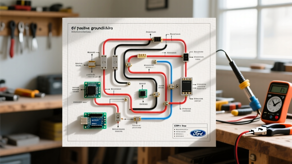
This comprehensive walkthrough provides a step-by-step wiring diagram for Ford 8N tractor restorations, focusing on the original 6V configuration. Whether you are rebuilding a front-mount distributor model or troubleshooting a side-mount, this guide delivers actionable, technician-level specifications to ensure your 8N starts reliably and charges correctly.
Early vs. Late 8N Electrical Differences
Before cutting any wire, you must identify your tractor's production year. Ford made a significant mid-production change to the distributor and ignition layout, which directly impacts your wiring routing.
| Feature | Early 8N (1947 - Mid 1950) | Late 8N (Mid 1950 - 1952) |
|---|---|---|
| Distributor Type | Front-Mount (Driven off front of engine) | Side-Mount / Angle-Mount (Driven off side) |
| Ignition Coil Location | Mounted directly on top of distributor | Mounted on dash / firewall |
| Starter Button Location | Dash-mounted push button | Right-side transmission housing (foot-operated or hand) |
| Primary Wiring Harness | Shorter run to front distributor | Longer run down to side engine block |
Required Tools and Wire Gauge Specifications
Using the correct wire gauge is non-negotiable. A 6-volt system draws twice the amperage of a 12-volt system for the same wattage, meaning undersized wires will cause severe voltage drop, resulting in weak spark and dim lights. According to SAE International Wiring Standards, adhere to the following gauge requirements:
- Battery to Starter Switch: 10 AWG (Stranded copper, red or black insulation)
- Starter Switch to Ammeter & Main Harness: 10 AWG
- Ammeter to Generator Cutout / Ignition Feed: 14 AWG
- Lighting and Accessories: 14 AWG or 16 AWG
- Coil Primary Wire: 14 AWG
Pro Tip: Invest in a high-quality soldering iron (like the Weller WE1010) and adhesive-lined heat shrink tubing. Avoid crimp-only connectors in the engine bay; the heavy vibration of a 4-cylinder flathead tractor engine will shake mechanical crimps loose over time. Solder and seal every connection.
Step-by-Step Wiring Walkthrough
Step 1: Battery and Chassis Grounding
Begin by establishing the positive ground. Mount a heavy-duty 6V battery (Group 26 or 22NF, typically 450-600 CCA) in the battery box.
- Clean the chassis ground point on the battery box or frame rail down to bare, shiny metal using a wire wheel.
- Connect a 10 AWG positive ground cable from the positive (+) battery terminal to the chassis ground point. Secure with a 5/16-inch bolt and star washer.
- Do not connect the negative cable to the starter yet. Leave it isolated to prevent accidental shorting while routing the main harness.
Step 2: Starter Motor and Ammeter Circuit
The ammeter is the heart of the 8N's monitoring system. Because this is a positive-ground system, current flows from the chassis, through the loads, and back to the negative terminal of the battery. When the generator charges, it pushes current into the negative terminal.
- Route the 10 AWG negative cable from the battery's negative (-) terminal to the bottom terminal of the dash-mounted ammeter.
- Connect a second 10 AWG wire from the top terminal of the ammeter to the battery terminal on the starter switch (push-button).
- From the starter switch output terminal, run a heavy 10 AWG cable directly to the starter motor terminal.
- Polarity Check: If your ammeter is unmarked, wire it temporarily. Turn on the headlights (without starting). If the needle pegs to 'Discharge', your wiring is correct. If it pegs to 'Charge', swap the two wires on the back of the ammeter.
Step 3: Ignition Switch, Ballast Resistor, and Coil
The Ford 8N uses a 6V coil that requires a ballast resistor to prevent overheating once the engine is running. Bypassing the Ford 9N-12250 (or modern 50-8508) ceramic resistor is a common mistake that will boil the coil's internal tar and destroy it within hours.
- Run a 14 AWG wire from the ignition switch 'BAT' terminal to one side of the ceramic ballast resistor mounted on the dash.
- Run a second 14 AWG wire from the other side of the resistor to the negative (-) terminal on the front-mount coil (or the terminal marked 'SW' on a side-mount coil).
- Connect the coil's positive (+) terminal to the chassis ground via the distributor housing (front-mount) or a dedicated ground wire (side-mount).
- Route the high-tension spark plug wires. Ensure the firing order is 1-2-4-3. The rotor turns counter-clockwise on the front-mount distributor.
Step 4: Generator and Cutout Relay Polarization
Early 8Ns utilize a 3-brush generator with a simple cutout relay (not a full voltage regulator). The cutout relay prevents the battery from discharging back into the generator when engine RPM drops.
- Mount the generator and connect the heavy 10 AWG output wire from the generator's 'GEN' terminal to the 'GEN' terminal on the cutout relay.
- Run a 10 AWG wire from the 'BAT' terminal on the cutout relay to the ammeter's main harness feed (the same post that feeds the ignition switch).
- CRITICAL STEP - Polarization: Before starting the engine, you must polarize the generator to match the positive-ground system. Take a jumper wire and briefly touch one end to the 'BAT' terminal of the cutout relay and the other end to the 'GEN' terminal. You should see a small spark. This aligns the generator's magnetic field. Skipping this will cause the generator to charge backwards, instantly welding the cutout relay contacts shut and draining your battery.
Common Wiring Failure Modes and Edge Cases
Even with a perfect wiring diagram for Ford 8N tractor restorations, environmental factors and worn components can cause edge-case failures. Consult the expert archives at Yesterday's Tractors for deep-dive community troubleshooting, but keep these primary failure modes in mind:
1. The 'Pegged' Ammeter at High RPM
If your ammeter pins to the maximum charge rate as you rev the engine, your cutout relay is likely stuck closed, or you have accidentally wired a 12V alternator into a 6V harness without a step-down resistor. In a stock 6V 3-brush generator system, output is mechanically limited by the third brush. If it's overcharging, the third brush adjustment ring inside the generator has likely vibrated out of position.
2. Intermittent Spark Under Load
When the tractor is idling, it runs fine, but bogs down or backfires when engaging the PTO. This is almost always a voltage drop issue. Check the grounding strap between the engine block and the chassis. The engine sits on rubber motor mounts; without a dedicated braided ground strap (minimum 10 AWG), the ignition coil cannot pull sufficient current from the chassis to fire the plugs under heavy load.
3. Melted Ignition Switch Terminals
Original bakelite ignition switches degrade over 70 years. If the internal contacts are pitted, they create high resistance, generating massive heat. If your switch feels hot to the touch after 10 minutes of runtime, replace it with a modern heavy-duty toggle switch rated for at least 20 amps, or source a high-quality reproduction from a trusted dealer like those listed on TractorHouse.
Expert Warning: Never attempt to jump-start a 6V positive-ground 8N using a modern 12V negative-ground truck. The reverse polarity will instantly fry the ammeter, weld the generator cutout relay, and can cause the battery to vent explosive hydrogen gas. Always use a dedicated 6V jumper pack or a secondary 6V battery wired positive-to-positive and negative-to-negative.
Final Inspection and Testing
Before turning the key, perform a continuity check. Disconnect the battery ground. Use a multimeter to verify there is no dead short between the negative battery cable (disconnected) and the chassis. Reconnect the ground. Turn on the ignition switch (do not crank). The ammeter should read a slight discharge (2-4 amps) indicating the coil is energized. Engage the starter. Once the engine catches and settles at a fast idle (approx. 800 RPM), the ammeter should smoothly swing to a positive charge (5-10 amps) and taper off as the battery reaches full capacity. If it holds steady, your wiring diagram execution is flawless, and your Ford 8N is ready for the field.