
Decoding the Club Car 48V Electrical Architecture
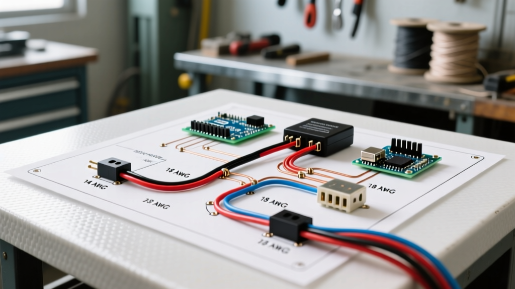
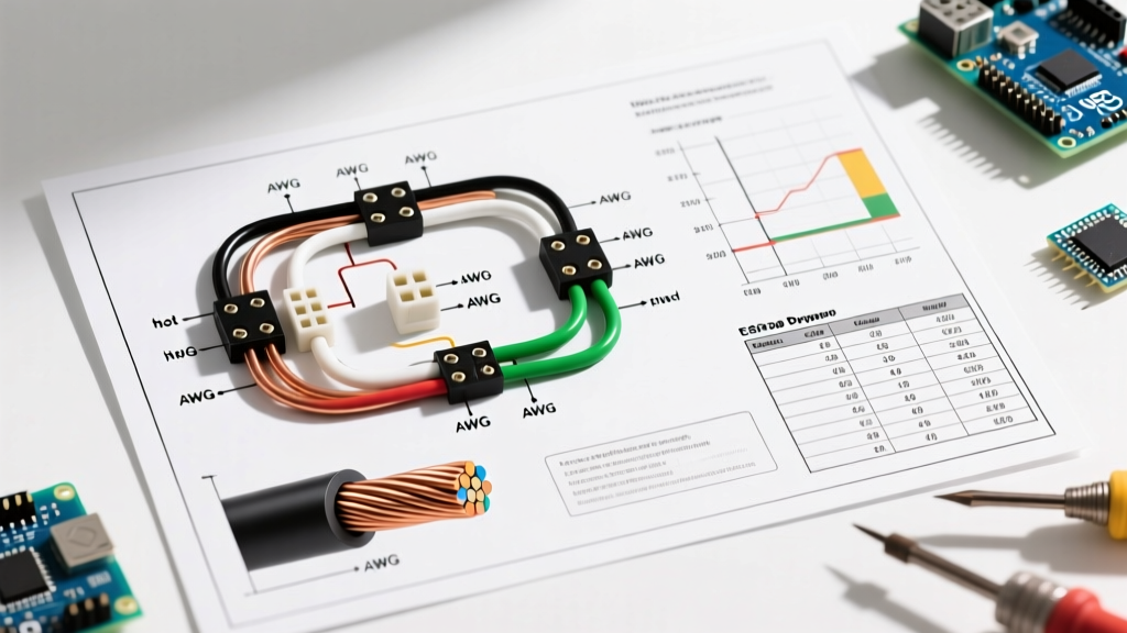
Understanding the wiring diagram for Club Car 48 volt systems is essential for any DIY mechanic, fleet technician, or golf cart enthusiast. Whether you are restoring a classic 1996-2014 Club Car DS or troubleshooting a modern Precedent IQ platform, the 48-volt architecture relies on a precise balance of high-current power delivery and low-voltage signal logic. A single misrouted 16 AWG signal wire or a degraded 2 AWG battery cable can result in catastrophic controller failure, welded solenoid contacts, or complete electrical blackouts.
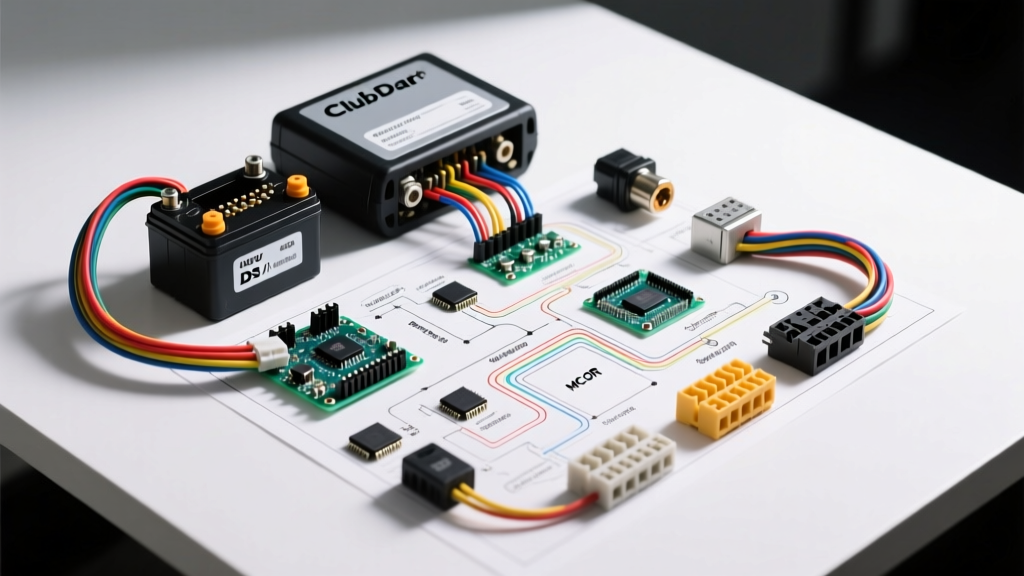
This comprehensive vehicle-specific guide breaks down the exact wiring topologies, component specifications, and diagnostic procedures required to maintain, repair, or upgrade your 48V Club Car in 2026. We will cover the main power loop, the critical precharge circuit, the Motor Controller Output Regulator (MCOR), and the necessary wiring modifications for modern lithium conversions.
48V Battery Bank Topologies and Cable Routing
The foundation of the Club Car 48V wiring diagram is the battery bank. While the controller simply 'sees' 48V to 52V, the physical wiring configuration drastically impacts your cart's torque, runtime, and maintenance requirements. Main battery cables must always be 2 AWG or 4 AWG stranded copper to handle the 300A+ peak draw of the stock 10kW motor without excessive voltage drop.
Series Wiring Configurations
| Configuration | Battery Type | Total Capacity (Approx.) | Wiring Complexity | 2026 Replacement Cost |
|---|---|---|---|---|
| 6 x 8V | Trojan T-875 (8V) | 150 Ah @ 20hr | Moderate (5 series jumpers) | $1,100 - $1,400 |
| 8 x 6V | Trojan T-105 (6V) | 225 Ah @ 20hr | High (7 series jumpers) | $1,300 - $1,600 |
| 4 x 12V | Deep Cycle 12V | 150 Ah @ 20hr | Low (3 series jumpers) | $900 - $1,200 |
According to deep-cycle battery maintenance guidelines published by Trojan Battery Technical Support, maintaining equal cable lengths and applying dielectric grease to all series jumper connections is critical to prevent uneven discharge rates across the 48V bank. When wiring the main positive (B+) and main negative (B-) to the controller, always route the B+ through the main solenoid and the B- directly to the controller's heavy-gauge negative terminal.
Step-by-Step IQ 48V Wiring Diagram Routing
The Club Car IQ system separates high-amperage traction power from low-amperage logic circuits. Here is the exact signal flow for the primary wiring harness.
1. Key Switch and Direction Selector (16 AWG Logic)
The 48V logic circuit begins at the key switch. When turned to 'ON', 48V is sent via a 16 AWG red wire to the Forward/Reverse (F/R) microswitch assembly.
- Forward Position: Routes 48V to the controller's 'Key Switch' input pin and the solenoid activation coil.
- Reverse Position: Routes 48V through the reverse buzzer circuit and limits the controller's output speed via the reverse-limit microswitch.
2. The Tow/Run Switch and OBC Integration
Located under the passenger seat, the Tow/Run switch is a vital safety and charging interlock.
- RUN Mode: Completes the circuit between the battery pack and the On-Board Computer (OBC), allowing the cart to drive and the OBC to regulate charging.
- TOW Mode: Physically disconnects the OBC and the controller's logic power. Warning: Leaving the cart in TOW mode for extended periods without a charger connected will result in parasitic drain from the solenoid coil and MCOR, leading to deep sulfation of lead-acid batteries.
3. Solenoid Activation and the Precharge Circuit
The heavy-duty solenoid (typically an Albright SW200 or Club Car OEM part #1014336) acts as the main contactor. However, wiring the solenoid coil directly without a precharge resistor is a guaranteed path to failure.
Critical Engineering Note: The Club Car IQ controller contains large internal filter capacitors. When the solenoid engages, these capacitors act as a dead short for a fraction of a second, drawing thousands of amps. The 250-ohm, 2-watt precharge resistor wired across the solenoid's large terminals allows a small trickle of current to slowly charge these capacitors before the main contacts close, preventing the contacts from welding together.
MCOR and Throttle Signal Wiring
Unlike older V-Glide systems that used physical microswitches, the IQ system utilizes a Motor Controller Output Regulator (MCOR), specifically the MCOR3 or MCOR4 units. The MCOR is a Hall-effect or potentiometer-based sensor that translates pedal pressure into a 0-5V signal for the controller.
MCOR Pinout and Voltage Sweeps
The MCOR connects to the controller via a 3-pin Deutsch or Molex connector. When diagnosing throttle issues, use a digital multimeter (such as a Fluke 117) to back-probe the signal wire while slowly depressing the accelerator pedal.
- Pin 1 (5V Reference): Supplied by the controller. Must read exactly 5.0V DC with the key on.
- Pin 2 (Ground): Controller logic ground. Must read 0.0V.
- Pin 3 (Signal Output): Should read 0.8V to 1.0V at rest (pedal up), and sweep smoothly to 3.4V to 3.6V at full throttle. Any sudden voltage drops or 'dead spots' during the sweep indicate internal track wear, requiring immediate MCOR replacement (approx. $140-$180 for OEM units).
Advanced Diagnostics: Voltage Drop Testing
When a Club Car 48V system exhibits sluggish acceleration or sudden shutdowns under load, amateur mechanics often blindly replace the controller or motor. As a domain expert, you must perform a voltage drop test to identify high-resistance connections. The NFPA 70 National Electrical Code outlines strict parameters for voltage drop in DC mobility applications to prevent thermal runaway.
How to Perform a 48V Load Test
- Set your multimeter to DC Volts.
- Place the jacks on the cart and elevate the rear wheels safely.
- Connect the multimeter's black lead to the main battery negative post.
- Connect the red lead to the controller's B+ terminal (past the solenoid).
- Depress the throttle to engage the motor.
- Analysis: If the voltage at the controller drops below 42V while the battery bank reads 48V, you have a high-resistance fault in the solenoid contacts, the main fuse, or the 2 AWG cable crimps. A healthy circuit should never drop more than 0.5V under load.
Troubleshooting Matrix: Common 48V Failure Modes
| Symptom | Probable Root Cause | Diagnostic Action | Expected Specification |
|---|---|---|---|
| Solenoid clicks, cart won't move | Welded solenoid contacts or failed motor brushes | Check voltage across large solenoid terminals while pressing pedal | 0.0V (Closed) or 48V (Open) |
| No click, completely dead cart | Blown 10A inline fuse or broken F/R microswitch | Continuity test on 16 AWG red wire from key switch | Less than 1.0 Ohm |
| Cart moves in reverse only | Failed forward microswitch in F/R assembly | Bypass forward switch with jumper wire | Cart moves forward |
| Controller beeps 4 times | HPD (High Pedal Disable) fault | Check MCOR rest voltage; ensure pedal returns fully | 0.8V - 1.0V at rest |
2026 Guide: 48V Lithium (LiFePO4) Conversion Wiring
Upgrading from lead-acid to a 48V LiFePO4 lithium battery is the most popular modification in 2026, reducing cart weight by up to 300 lbs and eliminating maintenance. However, the wiring diagram requires specific alterations to protect the Battery Management System (BMS).
Required Wiring Modifications for Lithium
- Bypass the OBC: The stock Club Car OBC is programmed for lead-acid charge curves and will severely undercharge or damage lithium cells. You must wire the charger directly to the battery pack's charge port, bypassing the OBC entirely.
- Remove the Mechanical Tow/Run Switch: Lithium BMS units feature internal electronic shut-offs. Leaving the mechanical Tow/Run switch in the circuit introduces unnecessary resistance. Wire a heavy-duty BMS kill-switch or a marine-grade battery disconnect directly to the BMS communication wire.
- Solenoid Precharge Retention: Even with lithium, the controller's capacitors require precharging. Keep the 250-ohm resistor wired across the solenoid to prevent BMS over-current trips caused by instantaneous inrush current.
For comprehensive data on lithium-ion thermal stability and BMS integration in light electric vehicles, refer to the ongoing mobility research published by the National Renewable Energy Laboratory (NREL). When selecting a lithium pack, ensure the BMS is rated for a continuous discharge of at least 100A and a peak surge of 400A to accommodate the Club Car's high starting torque requirements.
Final Safety and Torque Specifications
When finalizing your wiring diagram implementation, adherence to torque specifications is non-negotiable. Under-torqued 2 AWG battery lugs will arc and melt the battery posts.
- Battery Terminal Nuts (5/16 inch): Torque to 90-110 in-lbs (7.5-9.2 ft-lbs).
- Solenoid Large Posts (3/8 inch): Torque to 120-140 in-lbs (10-11.6 ft-lbs).
- Controller Bus Bars: Torque to manufacturer spec, typically 80-100 in-lbs, and apply a thin layer of NO-OX-ID A-Special conductive grease to prevent galvanic corrosion between copper lugs and aluminum/tinned bus bars.