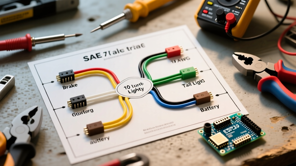

The Legal Framework: DOT and SAE Standards for Trailer Brakes
Wiring a trailer with electric brakes is not merely a convenience; it is a critical safety system governed by strict federal and state regulations. When you are searching for a reliable wiring diagram for a trailer with brakes, you must look beyond basic connectivity and focus on code compliance, voltage drop mitigation, and fail-safe mechanisms. In 2026, with the rise of heavy-duty electric trucks towing massive payloads, the electrical demands on trailer braking systems are higher than ever. A poorly executed wiring harness can lead to thermal runaway, melted connectors, or catastrophic brake failure on steep descents.
The two primary governing bodies for trailer wiring in the United States are the Department of Transportation (DOT) and the Society of Automotive Engineers (SAE). Specifically, 49 CFR § 393.43 mandates that any trailer equipped with electric brakes must have a breakaway system capable of holding the brakes in the applied position for at least 15 minutes in the event of a complete disconnect from the tow vehicle. Furthermore, the National Highway Traffic Safety Administration (NHTSA) emphasizes that proper grounding and wire gauge selection are the leading factors in preventing trailer fires and brake fade.
The 7-Way RV Blade Pinout: Navigating the SAE vs. RV Color Code Discrepancy
The most common point of failure in DIY trailer wiring stems from a historical discrepancy between the official SAE J286 standard and the de-facto RV industry standard. While the physical 7-way blade connector (such as the Hopkins H20046 or Pollak PK12706) is universal, the internal wire color codes differ for three critical pins. Failing to recognize this difference is a primary cause of short circuits and blown fuses during DOT inspections.
| Pin Position | Function | RV Industry Standard Color | SAE J286 Standard Color | Wire Gauge (AWG) |
|---|---|---|---|---|
| 1 (Ground) | Chassis / System Ground | White | White | 10 AWG or 8 AWG |
| 2 | 12V Auxiliary / Charge | Black | Red | 12 AWG or 10 AWG |
| 3 | Tail / Running Lights | Brown | Brown | 16 AWG |
| 4 | Left Turn / Stop | Yellow | Yellow | 16 AWG |
| 5 | Right Turn / Stop | Green | Green | 16 AWG |
| 6 | Electric Brakes (Output) | Blue | Brown | 10 AWG |
| 7 | Backup Lights / Aux | Purple | Black | 16 AWG or 14 AWG |
Expert Warning: Always wire your 7-way plug according to the RV Industry Standard (Pin 2 = Black, Pin 6 = Blue, Pin 7 = Purple). Modern brake controllers, including the industry-standard Tekonsha Prodigy P3 (90195), and almost all factory-installed truck tow packages are pre-wired to the RV color code, not the SAE standard. Mixing these will send 12V auxiliary power directly into your trailer's brake magnets, instantly frying them.
Wire Gauge Sizing and Voltage Drop Mitigation
Code compliance requires that wire gauges be sized not just for amperage capacity, but for voltage drop over the length of the trailer. Electric brake magnets typically draw 3.0 to 3.5 amps each at 12 volts. A dual-axle trailer (4 brakes) can pull up to 14 amps during a maximum panic stop.
If you use standard 14 AWG wire for a 25-foot run to the rear axle, the voltage drop will exceed 1.5 volts. This means your rear brakes will only receive ~10.5 volts, resulting in a 20% reduction in braking torque and causing the front axle to do all the work, leading to premature wear and trailer sway.
Recommended Wiring Specs for Dual-Axle Trailers
- Main Brake Feed (Pin 6 to Junction Box): 10 AWG Copper (Stranded). Cost: ~$1.20/ft for Southwire 10/2 Duplex.
- Axle Cross-Overs and Drops: 12 AWG Copper. Must be routed through flexible loom to prevent debris tearing.
- Ground Return (Pin 1 to Chassis): 10 AWG or 8 AWG. Never rely on the trailer hitch ball for a ground return. A dedicated 10 AWG white wire must run the entire length of the trailer back to the main junction box.
Wiring the Breakaway System: 49 CFR § 393.43 Compliance
Any trailer with a Gross Vehicle Weight Rating (GVWR) over 3,000 lbs equipped with electric brakes must have a DOT-compliant breakaway system. The Hopkins 20001 Breakaway Kit (approx. $25) includes a 12V 5Ah Sealed Lead Acid (SLA) battery, a charger, and a pull-pin switch.
Here is the exact step-by-step wiring sequence to ensure the breakaway system operates independently of the tow vehicle's wiring, as required by law:
- Battery Positive (+) connects to one terminal of the breakaway pull-pin switch.
- The second terminal of the pull-pin switch splices directly into the Blue (RV standard) brake feed wire between the 7-way plug and the trailer's front junction box.
- Battery Negative (-) connects to the main trailer chassis ground via a dedicated 10 AWG white wire with a star-washer ring terminal.
- Breakaway Charger Wiring: The charger's Black wire splices into the 12V Auxiliary pin (Pin 2, Black wire). The charger's Red wire connects to the battery Positive (+). The charger's White wire connects to the battery Negative (-).
Inspection Tip: DOT inspectors will pull the breakaway pin and use a multimeter to verify that 12V+ is reaching the brake magnets. If your breakaway battery is dead or wired in parallel with the brake controller output without a blocking diode, it will fail inspection.
Brake Controller Integration: Tekonsha Prodigy P3 (90195)
The Tekonsha Prodigy P3 (Model 90195, retail ~$160) remains the gold standard for proportional trailer brake controllers due to its diagnostic capabilities and code-compliant power management. To integrate the P3 into your tow vehicle's wiring harness leading to the 7-way receptacle, follow this 4-wire schematic:
- White Wire (Ground): Must be terminated directly to the vehicle's negative battery terminal or a dedicated chassis ground stud. Do not ground this to the dashboard frame.
- Black Wire (12V Power Input): Routes to the vehicle's positive battery terminal via a 30-amp auto-reset circuit breaker (Bussmann 18130). This prevents catastrophic fires if the blue output wire shorts to ground.
- Red Wire (Stoplight Switch): Taps into the vehicle's cold-side stoplight circuit. This signals the P3 to initiate the proportional braking algorithm.
- Blue Wire (Brake Output): Routes to Pin 6 of the vehicle's 7-way receptacle. Use 10 AWG wire for this run to minimize voltage drop between the controller and the trailer plug.
Critical Code Violations and Common Failure Modes
When auditing trailer wiring diagrams for safety, avoid these frequent and dangerous mistakes that immediately flag DOT and commercial vehicle inspectors:
1. The 'Chassis Ground' Fallacy
Many older diagrams suggest grounding the brake magnets directly to the trailer axle. Because axles are connected via suspension springs and pivot points, electrical resistance can fluctuate wildly. Correction: Run a dedicated 12 AWG ground wire from every individual brake magnet back to a central, sealed junction box, and tie it to the main 10 AWG ground wire running to the 7-way plug.
2. Using Standard Butt Connectors
Using non-sealed, vinyl-insulated butt connectors under a trailer chassis guarantees corrosion within 12 months. Moisture wicks into the crimp, creating a high-resistance joint that generates heat and drops voltage. Correction: Use only dual-wall, adhesive-lined heat shrink connectors (e.g., Wirefy 12-10 AWG Heat Shrink Butt Connectors). The internal polyamide adhesive melts and seals the joint completely against water and road salt.
3. Undersized Circuit Breakers
Using a standard automotive blade fuse for the main brake feed is a code violation. Blade fuses do not reset and can fail under high-vibration environments. Correction: Install a 30A or 40A Type 1 (auto-reset) circuit breaker within 18 inches of the tow vehicle's battery positive terminal, as mandated by RVIA and NFPA 1192 standards.
Frequently Asked Questions
Can I use a 4-way flat to 7-way round adapter for trailer brakes?
No. A standard 4-way flat connector lacks the dedicated Pin 6 (Blue wire) circuit required for electric brakes, as well as the 12V auxiliary circuit required to charge a breakaway battery. Adapters that claim to enable brakes without a dedicated brake controller and 10 AWG power feed are illegal for highway use and highly dangerous.
How often must the breakaway battery be replaced to remain DOT compliant?
While the law does not specify a timeframe, it specifies performance: the battery must hold the brakes for 15 minutes. Standard 12V 5Ah SLA batteries degrade rapidly in extreme temperatures. Best practice dictates testing the battery with a load tester every 6 months and replacing it every 2 to 3 years (Cost: ~$20 for a Mighty Max ML5-12 replacement).
For further technical reference on commercial towing standards, consult the eTrailer Wiring FAQ and SAE Standards Guide, which provides exhaustive schematics for heavy-duty and commercial applications.