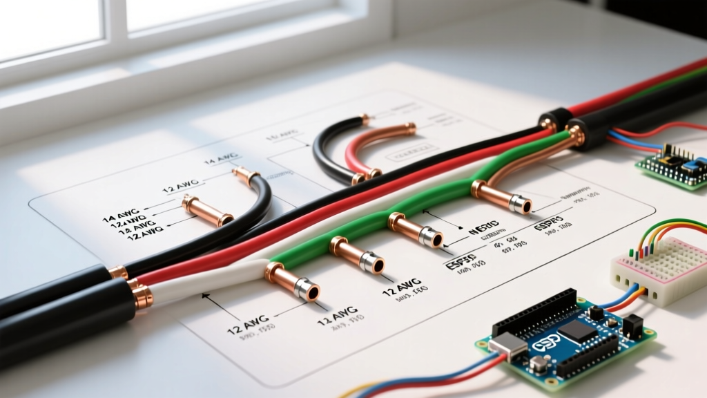

The Critical Link Between Schematics and Physical Wire
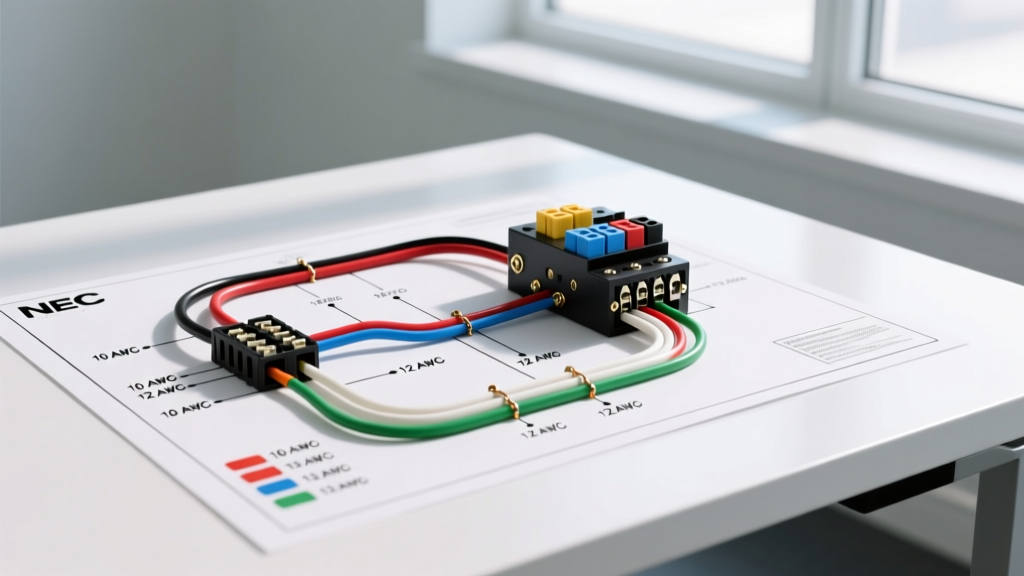
Reading an electrical home wiring diagram is only the first step in a safe residential installation or renovation. While the schematic provides the logical roadmap of your circuits, translating those lines into physical reality requires a strict adherence to wire gauge (AWG) and insulation color codes. A mismatch between the diagram's intended load and the physical wire installed is one of the leading causes of residential electrical fires.
As of 2026, the National Electrical Code (NEC) continues to enforce rigorous standards for conductor sizing and identification. Whether you are upgrading a main service panel, wiring a new smart-home subpanel, or simply adding a 20-amp kitchen receptacle, understanding how to map your electrical home wiring diagram to physical NM-B (Romex) or THHN conductors is non-negotiable. This guide bridges the gap between schematic symbols and the copper running through your walls.
Expert Insight: Never assume the line weight on a printed schematic perfectly correlates to wire thickness. Always cross-reference the diagram's Bill of Materials (BOM) or legend. A heavy line might indicate a 6 AWG feeder, but without the legend, it is merely a graphical convention.
NEC Wire Color Codes for Residential AC Power
Color coding is the primary visual safety mechanism in electrical work. According to NEC Articles 200, 210, and 250, specific colors are legally mandated for specific functions in residential alternating current (AC) systems. When reviewing your electrical home wiring diagram, the lines are often labeled with these color abbreviations (e.g., BK, WH, GR).
Standard 120V/240V Residential Color Matrix
| Wire Color | NEC Function | Diagram Label | Termination Point |
|---|---|---|---|
| Black | Ungrounded (Hot) - Phase 1 | BK / BLK | Brass/Gold Screw on Receptacle |
| Red | Ungrounded (Hot) - Phase 2 / Switch Leg | RD / RED | Brass Screw / 240V Breaker |
| White | Grounded (Neutral) | WH / WHT | Silver Screw / Neutral Bus Bar |
| Gray | Grounded (Neutral) - 277V/480V | GY / GRY | Neutral Bus (Rare in standard homes) |
| Green / Bare | Equipment Grounding Conductor (EGC) | GR / BARE | Green Screw / Ground Bus Bar |
Note on Multi-Wire Branch Circuits (MWBC): If your diagram shows a shared neutral circuit (two hot wires sharing one neutral), NEC 210.4 requires the ungrounded conductors to be distinctly colored (typically Black and Red) and the neutral (White) to be sized to handle the maximum unbalanced load.
Wire Gauge (AWG) and Ampacity Reference Chart
The American Wire Gauge (AWG) system dictates the physical diameter of the copper conductor. Counterintuitively, a lower AWG number means a thicker wire with higher ampacity. When sizing wire for your electrical home wiring diagram, you must follow NEC Article 240.4, which mandates that the overcurrent device (breaker) must be rated no higher than the ampacity of the wire.
2026 Residential Copper Ampacity Matrix (60°C / 75°C Column)
| AWG Size | Max Ampacity (Copper) | Standard Breaker Size | Common Residential Application | Approx. 2026 Cost (250ft NM-B) |
|---|---|---|---|---|
| 14 AWG | 15 Amps | 15A | General lighting, bedroom receptacles | $105 - $125 |
| 12 AWG | 20 Amps | 20A | Kitchen, bathroom, laundry, garage | $140 - $165 |
| 10 AWG | 30 Amps | 30A | Electric water heater, window AC units | $210 - $240 |
| 8 AWG | 40 Amps | 40A | HVAC condenser, electric cooktop | $320 - $360 |
| 6 AWG | 55 Amps | 50A | Electric range, main subpanel feeder | $450 - $510 |
| 4 AWG | 70 Amps | 60A | EV Level 2 charger, large subpanel | $650 - $720 |
| 2 AWG | 95 Amps | 100A | Main service entrance feeder | $900+ (THHN in conduit) |
Pricing Note: Copper commodity prices fluctuate. The costs above reflect early 2026 retail averages for Southwire and CerroWire NM-B (Romex) cables at major home improvement centers.
Translating Diagram Scenarios to Physical Installs
To demonstrate how to apply this reference, let us examine three common scenarios found in a modern electrical home wiring diagram and the physical execution required.
Scenario A: The 20-Amp Kitchen Small Appliance Branch Circuit
The Diagram: Shows a 20A breaker feeding a series of GFCI and standard duplex receptacles above the kitchen counter. The line is labeled '12/2 w/ Grd'.
The Execution: You must pull 12 AWG copper wire. While 14 AWG can physically carry 15 amps, NEC 210.11(C)(1) strictly requires 20-amp circuits for kitchen small appliance branches. Using 14 AWG wire on a 20A breaker is a severe code violation and a primary fire hazard, as the breaker will not trip before the 14 AWG wire overheats and melts its insulation.
Scenario B: The 50-Amp Electric Range Circuit
The Diagram: Indicates a 50A double-pole breaker feeding a NEMA 14-50R receptacle. The schematic specifies '6/3 NM-B'.
The Execution: A 6/3 NM-B cable contains three insulated 6 AWG conductors (Black, Red, White) and one bare 10 AWG ground wire. The 50A breaker is perfectly matched to the 55-amp capacity of 6 AWG copper at 60°C. Edge Case: If the diagram specifies a 60A range, you must upgrade to 4 AWG copper or 2 AWG aluminum, as 6 AWG is legally capped at a 50A breaker for standard residential terminations.
Scenario C: The Detached Garage Subpanel (The Voltage Drop Trap)
The Diagram: Shows a 60A subpanel in a detached garage, fed by a 60A breaker in the main house, with a line labeled '6 AWG Copper, 150 feet'.
The Execution: This is where blind adherence to a diagram fails. According to NEC Informational Note 210.19(A), a 3% voltage drop is recommended for branch circuits, and 5% total. Running 6 AWG copper 150 feet at a continuous 48-amp load (80% of 60A) results in a voltage drop of roughly 4.8% just on the feeder. To maintain optimal efficiency for modern EV chargers or heavy power tools in the garage, a professional electrician will upsize the physical wire to 4 AWG or even 3 AWG copper, despite the diagram calling for 6 AWG. Always calculate voltage drop using the formula: VD = (2 x K x I x L) / CM.
Smart Home & Low-Voltage Diagram Overlaps
In 2026, a comprehensive electrical home wiring diagram rarely stops at 120V/240V AC power. Modern schematics integrate low-voltage PoE (Power over Ethernet) lighting, smart thermostats, and motorized blinds.
- Blue/Yellow/Orange Pairs: Typically denote Cat6/Cat6a data cables. Never run these in the same physical conduit or bored hole as AC power without a physical divider, per NEC Article 725.
- 18 AWG to 16 AWG (Red/White): Standard for 24V HVAC thermostat control wires and doorbell transformers.
- 12 AWG (Purple/Pink): Often used in commercial settings for 277V, but in high-end 2026 residential smart homes, purple jacketed 12 AWG is sometimes specified for dedicated PoE++ lighting circuits (Class 2 power).
Troubleshooting Edge Cases and Code Violations
When auditing an existing home against its original electrical home wiring diagram, look out for these common, dangerous discrepancies:
- The 'Double-Tapped' Neutral: The diagram shows one neutral per terminal. In the panel, you find two white wires crammed under a single neutral bus screw. This violates NEC 408.41 and can cause neutral overloading and arcing.
- Aluminum to Copper Pigtailing without AlumiConn: Older diagrams (pre-1975) may show 10 AWG aluminum wire for 30A dryers. If a previous homeowner spliced this to modern 10 AWG copper using standard wire nuts, it is a massive fire risk. You must use ESFI-approved AlumiConn lugs or COPALUM crimps.
- Missing Equipment Grounds: A diagram updated in the 1990s might show 2-prong receptacles replaced with 3-prong GFCIs. While NEC allows a GFCI to protect an ungrounded circuit (labeled 'No Equipment Ground'), the physical wire remains 14/2 without a ground. Do not plug sensitive surge-protected electronics into these outlets.
Frequently Asked Questions (FAQ)
Can I use 12 AWG wire on a 15-amp breaker?
Yes. NEC 240.4 allows you to use a larger wire (lower AWG number) on a smaller breaker. While 12 AWG is physically harder to bend and terminate on standard 15A receptacles, it is perfectly legal and actually reduces voltage drop. Many professionals exclusively use 12 AWG for all general-purpose circuits to simplify inventory and prevent future over-fusing.
Why does my diagram show a white wire connected to a switch?
In older electrical home wiring diagrams (and physical homes built before the 2011 NEC update), a 2-wire cable (Black/White) was often run from a switch loop to a light fixture. The white wire was used as the 'hot' feed to the switch, and the black wire returned the switched hot to the light. Under current NEC 200.7(C)(2), if a white wire is used as an ungrounded (hot) conductor, it must be permanently re-identified with black tape or paint at both ends. The 2011 NEC also mandated a dedicated neutral at switch boxes to accommodate modern smart switches.
How do I read the ground wire size on a schematic?
Standard NM-B cable includes an equipment grounding conductor (EGC) that is smaller than the current-carrying conductors. For 14, 12, and 10 AWG circuits, the bare ground is 14 AWG. For 8 and 6 AWG circuits, the ground is 10 AWG. If your diagram specifies a separate ground wire (common in THHN conduit runs), refer to NEC Table 250.122 to size the ground based on the breaker size, not the circuit wire size.