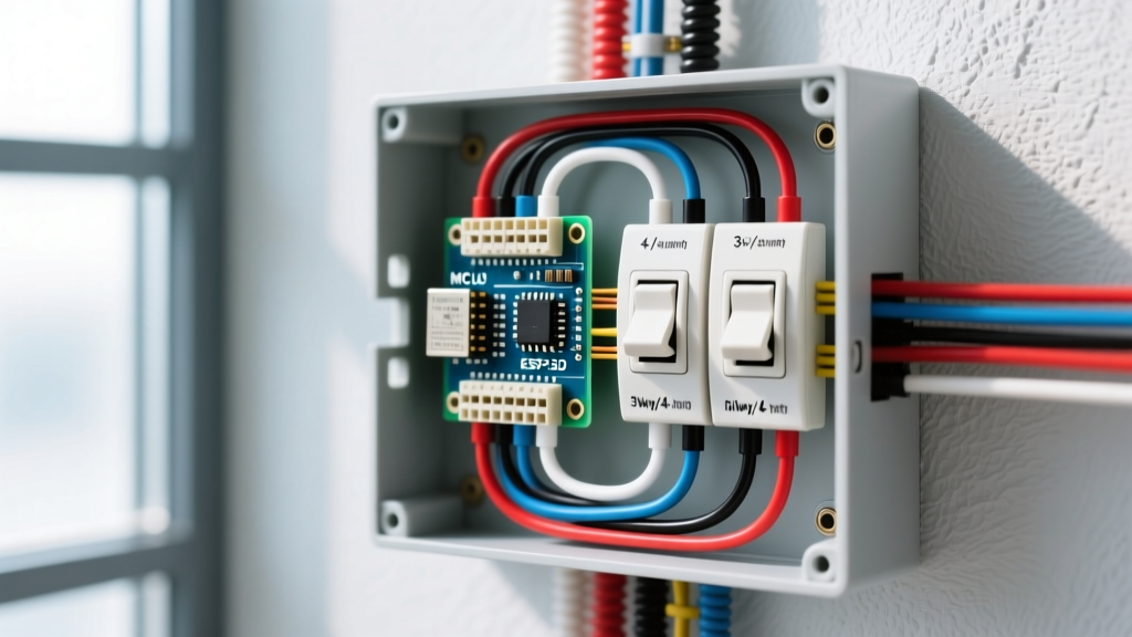

The Architecture of Multi-Point Switching Circuits
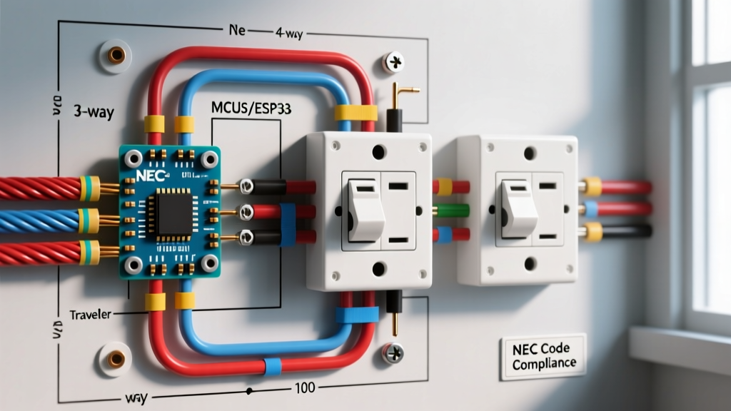
In commercial appliance repair facilities, large testing bays and long diagnostic corridors require lighting and ventilation control from three or more distinct locations. This is where standard single-pole and 3-way switches fall short. To achieve multi-point control, electrical professionals rely on a specific configuration: two 3-way switches bookending one or more 4-way switches. When interpreting 4 way wiring diagrams for switches, the most critical concept to grasp is that a 4-way switch never connects directly to the power source (line) or the load. It functions strictly as an intermediary reversing valve for the traveler circuit.
From an appliance wiring tutorial perspective, treating a 4-way switch like a standard break-point is a fundamental error. Internally, a 4-way switch is a Double-Pole, Double-Throw (DPDT) mechanism. It either passes the traveler wires straight through or crosses them in an 'X' pattern, altering the continuity path back to the final 3-way switch. Understanding this internal logic is the key to mastering complex, multi-location control systems for heavy-duty workshop environments.
Terminal Identification Matrix
Before stripping a single wire, you must accurately identify the terminal screws. Misidentifying the common terminal on a 3-way or mixing up the input/output pairs on a 4-way will result in a circuit that only works from one location. Consult the matrix below for standard North American wiring device terminal configurations.
| Switch Type | Terminal Count | Screw Color / Marking | Function & Wire Assignment |
|---|---|---|---|
| 3-Way (Line Side) | 3 + Ground | 1 Dark (Black/Copper), 2 Brass | Dark = Line (Hot); Brass = Travelers |
| 4-Way (Intermediary) | 4 + Ground | 2 Brass, 2 Dark (Black) | Brass = Input Travelers; Dark = Output Travelers |
| 3-Way (Load Side) | 3 + Ground | 1 Dark (Black/Copper), 2 Brass | Dark = Load (Switched Hot); Brass = Travelers |
Required Materials and Tooling for 20A Appliance Bay Circuits
When wiring lighting and ventilation relays in an appliance testing bay, a 15-amp circuit is often insufficient due to the inrush current of high-bay LED drivers and exhaust fan contactors. We recommend standardizing on 20-amp circuits using 12 AWG copper conductors.
- Wire: 12/3 NM-B (Romex) for the traveler runs between switches. The red, black, and white (re-identified) wires serve as the travelers and common feed.
- Switches: Commercial-grade 4-way devices like the Leviton 5604-2W (Decora style, approx. $14.50) or the Eaton 764W (heavy-duty toggle, approx. $9.00). Avoid residential-grade switches for high-cycle appliance bays.
- Strippers: Klein Tools 11055 wire strippers to ensure clean 3/4-inch jackets without nicking the 12 AWG copper.
- Meter: Fluke 117 True RMS Multimeter for non-contact voltage detection and continuity testing.
- Torque Driver: A calibrated torque screwdriver set to 14 in-lbs to secure terminal screws, preventing thermal arcing under continuous load.
Step-by-Step Execution: Wiring the Multi-Point Circuit
Follow this precise sequence to wire a 3-point control circuit (Line -> 3-Way -> 4-Way -> 3-Way -> Load). Ensure the main breaker is locked out and tagged out (LOTO) per OSHA electrical safety standards before beginning.
Phase 1: The Line-Side 3-Way Switch
- Route your 12/2 NM-B power feed into the first electrical box. Connect the bare copper to the ground pigtail and the white neutral to the neutral bus (neutrals do not connect to standard mechanical switches).
- Connect the black hot wire to the dark-colored common terminal on the first 3-way switch.
- Route a 12/3 NM-B cable from this box to the 4-way switch location. Connect the red and black wires of the 12/3 cable to the two brass traveler terminals on the 3-way switch.
Phase 2: The 4-Way Intermediary Switch
This is where most electricians make errors when reading 4 way wiring diagrams for switches. The 4-way switch has two distinct pairs of terminals: an 'IN' pair and an 'OUT' pair. They are usually differentiated by color (e.g., brass for IN, black for OUT) or by physical grouping on the device yoke.
- Take the 12/3 cable arriving from the first 3-way switch and terminate the red and black wires onto the brass (IN) terminals of the 4-way switch.
- Route a new 12/3 cable from the 4-way box to the final 3-way switch box.
- Terminate the red and black wires of this outgoing cable onto the dark (OUT) terminals of the 4-way switch.
- Pro Tip: If your 4-way switch does not color-code the terminals, look for the stamped 'LINE' and 'LOAD' or 'IN' and 'OUT' markings on the back housing. Never mix an IN and an OUT terminal on the same side of the switch.
Phase 3: The Load-Side 3-Way and Appliance Contactor
- At the final box, take the incoming 12/3 cable from the 4-way and connect its red and black wires to the brass traveler terminals of the second 3-way switch.
- Connect the dark common terminal of this second 3-way to the black wire of your 12/2 load cable heading to the appliance bay lighting or ventilation contactor coil.
- Splice all white neutral wires together with a wire nut (or WAGO 221 lever nut) and route them straight to the load. The switch leg only breaks the hot conductor.
NEC Compliance Note: According to NFPA 70 (National Electrical Code) Article 210.12, all 120V, single-phase, 15- and 20-ampere branch circuits supplying outlets in dwelling units (and increasingly in commercial repair lounges) must be protected by an Arc-Fault Circuit Interrupter (AFCI). Ensure your panel breaker is an AFCI/GFCI dual-function type if the circuit serves areas with grounded appliance chassis.
Heavy-Duty Appliance Integration: Controlling High-Amperage Loads
A standard 4-way switch is rated for 15A or 20A at 120VAC. It is never acceptable to wire a 4-way switch directly in series with a 240V appliance motor (like a commercial oven blower or a 3-phase compressor test rig). The internal contacts of a standard 4-way switch will arc violently and weld shut under 240V inductive loads.
The Solution: Use the multi-point 4-way switch circuit to control the 120V coil of a heavy-duty contactor (e.g., Eaton C25DND230, rated for 30A inductive). The 4-way switches safely manage the low-current 120V signal, while the contactor handles the 240V/30A+ appliance load. This methodology bridges the gap between standard architectural wiring diagrams and heavy appliance control logic.
Troubleshooting Common 4-Way Failure Modes
When a multi-point circuit fails, it is almost always due to traveler misidentification or a broken neutral splice. Use your Fluke 117 to perform the following diagnostic sequence.
Diagnostic Checklist
- Symptom: Circuit only works from one specific switch.
Diagnosis: The travelers on one of the 3-way switches are reversed, or the common terminal is misidentified. Use the multimeter in continuity mode (power off) to find the single terminal that shows continuity to one of the brass screws in one toggle position, and the other brass screw in the opposite position. That is your common. - Symptom: Switch works, but trips AFCI breaker instantly.
Diagnosis: A shared neutral violation. If the 12/3 traveler cable is routed through a metal junction box and the bare ground is touching the white neutral wire, or if the neutral is being switched instead of the hot leg, the AFCI will detect an imbalance and trip. Verify that only the hot leg passes through the switch terminals. - Symptom: Intermittent flickering under load.
Diagnosis: Back-stabbed push-in terminals. Residential-grade switches often use push-in wire traps that loosen under the thermal expansion of 12 AWG wire carrying 15+ amps. Always use the side-clamp terminal screws and torque to manufacturer specifications.
Smart Home and IoT Upgrades in Multi-Point Circuits
As appliance repair shops modernize in 2026, integrating IoT monitoring into lighting and ventilation is common. Upgrading a mechanical 4-way circuit to a smart system (like Lutron Caseta or Leviton Decora Smart) requires altering the wiring diagram entirely. Smart 4-way companion switches do not use physical traveler wires to pass current; instead, they use one traveler as a 120V signal wire and the other as a neutral return. Always consult the specific manufacturer's smart-switch schematic, as legacy 4 way wiring diagrams for switches do not apply to digital companion modules.
By adhering to strict terminal identification, utilizing commercial-grade hardware, and respecting the boundaries between 120V control signals and 240V appliance loads, you can build multi-point switching circuits that are both code-compliant and virtually indestructible in a high-traffic workshop environment.