
Engineering the Gatekeeper: Winch Solenoid Fundamentals
A modern 12,000-pound synthetic rope winch doesn't just pull heavy loads; it devours electrical current. Under maximum rated line pull, a standard 12V DC winch motor can draw between 350 and 450 amps. Routing this massive current directly through a dashboard switch, a handlebar toggle, or even a 2026-era wireless remote receiver would instantly vaporize the control wiring. This is where the winch solenoid (technically a high-amperage DC contactor) becomes the critical gatekeeper in your rig's electrical architecture.
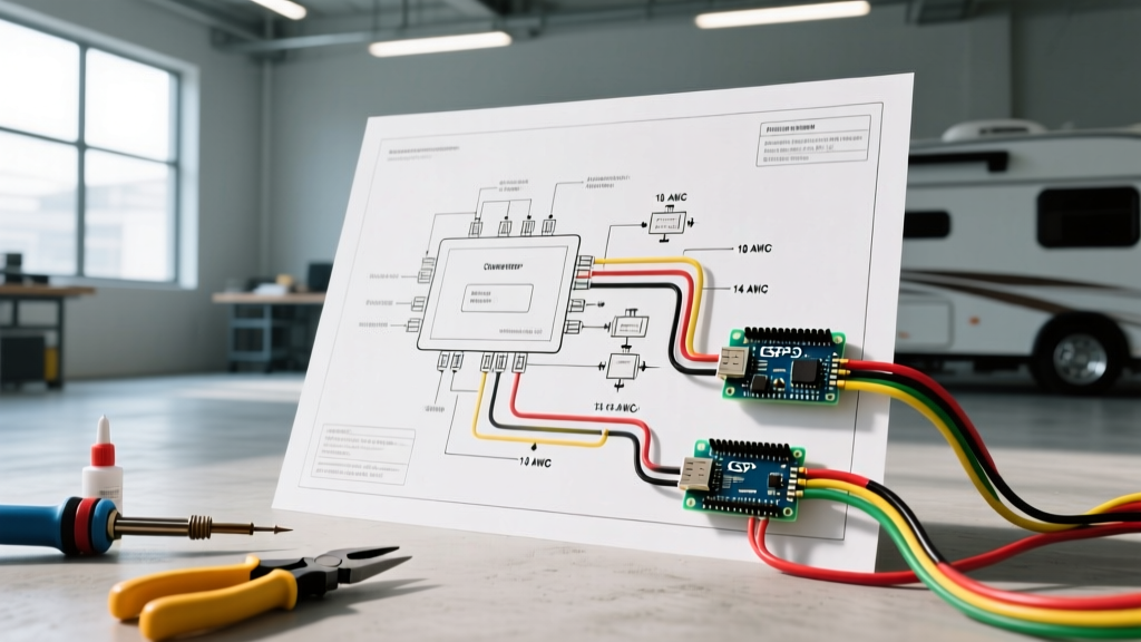
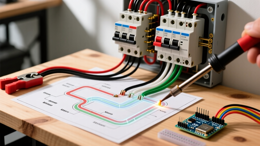
Planning your installation with a precise wiring diagram for winch solenoid integration ensures that your low-amperage control circuit remains entirely isolated from the high-current motor circuit. This prevents catastrophic electrical fires, minimizes voltage drop, and ensures reliable deployment when you are buried to the axles in mud. Below is a comprehensive installation planning guide tailored for off-road, marine, and heavy-duty recovery applications.
⚠️ Critical Safety Warning: Intermittent vs. Continuous DutyMost off-road winches ship from the factory with intermittent-duty solenoids. These are designed for a maximum continuous engagement of 45 to 60 seconds. If you use a winch for a prolonged, heavy-drag recovery without allowing the coil to cool, the internal copper windings will overheat, melt the insulation, and cause the main contacts to weld together. This results in a 'runaway winch' scenario where the motor continues to spool even after you release the remote button. Always monitor duty cycles during heavy pulls.
Component Selection Matrix: Choosing the Right Contactor
Before cutting any wire or crimping lugs, you must match the solenoid to your operational profile. Upgrading to a continuous-duty solenoid is highly recommended for frequent trail rigging, tow trucks, or marine capstan applications.
| Model / Brand | Duty Cycle | Max Inrush Amps | Approx. Price (2026) | Best Application |
|---|---|---|---|---|
| Warn 72631 | Intermittent | 400A | $85 - $95 | Standard OEM off-road replacement |
| Cole Hersee 24059-01 | Continuous | 300A (Cont.) | $65 - $75 | Heavy-duty recovery, marine, tow |
| Stens 435-845 | Intermittent | 250A | $35 - $45 | Light-duty ATV/UTV winches |
For deep-dive specifications on heavy-duty commercial contactors, referencing the Littelfuse/Cole Hersee solenoid catalog provides excellent engineering data on coil resistance and arc suppression.
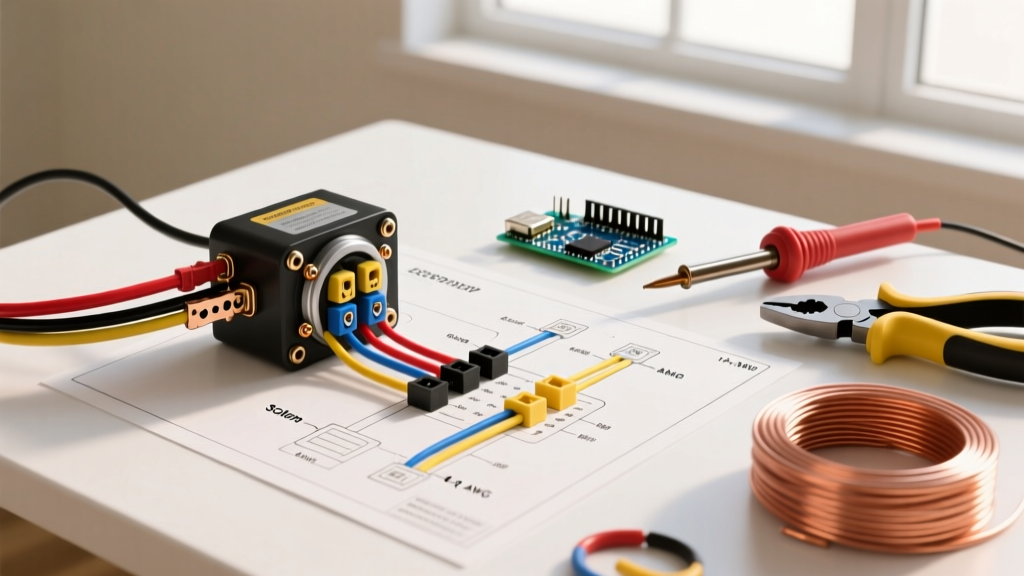
The Standard 4-Terminal Wiring Diagram for Winch Solenoid
While older or ultra-budget winches sometimes use a 3-terminal 'case-ground' solenoid (where the metal mounting bracket completes the ground circuit), the 4-terminal isolated ground configuration is the modern standard for reliable 12V DC systems. This prevents stray currents from traveling through the chassis or winch motor housing, which can cause erratic wireless remote behavior or galvanic corrosion in marine environments.
Terminal Mapping & Color Codes
- Terminal A (Large 5/16" Stud): Battery Positive (+). Connects directly to the vehicle's main battery positive post or a high-amperage distribution busbar. Wire Color: Red.
- Terminal B (Large 5/16" Stud): Winch Motor Positive (+). Connects to the positive post on the winch motor housing. Wire Color: Red (or Yellow for motor-side differentiation).
- Terminal C (Small #10 Stud): Ignition/Dash Trigger (+12V). Connects to the 'IN' or 'Power' terminal on your winch control box or wireless receiver. Wire Color: Blue or White.
- Terminal D (Small #10 Stud): Ground (-). Connects to the vehicle chassis or directly to the battery negative post. Wire Color: Black.
Pro-Tip: Always install a 150A to 200A marine-grade circuit breaker (like a Blue Sea Systems MIDI fuse) on the main battery feed before it reaches Terminal A. This protects the main 2 AWG cable in the event of a dead short against the chassis.
Step-by-Step Routing and Termination Protocol
Executing the physical installation requires attention to mechanical stress and environmental sealing. Follow these steps to ensure a factory-grade connection.
- Isolate the Power Source: Disconnect the negative battery terminal first, followed by the positive. Wait 5 minutes for any residual capacitance in wireless receiver modules to dissipate.
- Mounting Geometry: Mount the solenoid in a dry, ventilated area away from exhaust headers. If mounting near the winch motor, ensure the solenoid is positioned vertically with the terminals facing downward to prevent water pooling on the studs.
- Main Power Routing (High Current): Route the 2 AWG or 1/0 AWG battery cables. Keep them away from steering shafts and suspension components. Use split-loom tubing and zip-ties every 12 inches.
- Control Circuit Wiring (Low Current): Run 12 AWG stranded copper wire for the trigger and ground circuits. Install an inline 20A ATO blade fuse within 6 inches of the power source for the trigger wire.
- Crimping and Sealing: Never solder 2 AWG winch cables. Solder wicks into the wire strands, creating a brittle point that will snap under chassis vibration. Instead, use a hydraulic crimper for closed-end copper lugs, and seal them with 3:1 ratio adhesive-lined marine heat shrink.
- Torque Specifications: Tighten the large 5/16" terminal nuts to 120 in-lbs (10 ft-lbs). Apply a thin layer of dielectric grease over the assembled terminals to prevent oxidation.
For additional context on routing high-amperage DC cables through vehicle firewalls and chassis, the eTrailer wiring FAQ archives offer excellent visual guides on grommet usage and chassis grounding.
Wire Gauge Selection & Voltage Drop Mathematics
Undersized wiring is the leading cause of winch solenoid failure. When a winch pulls 400 amps through undersized wire, the resulting voltage drop starves the motor, causing it to overheat while the solenoid coil receives insufficient voltage to maintain a tight magnetic seal, leading to contact arcing.
| Winch Max Amp Draw | Cable Run (One Way) | Minimum AWG Required | Recommended AWG (Safety Margin) |
|---|---|---|---|
| Up to 250A | Under 10 ft | 4 AWG | 2 AWG |
| 250A - 400A | 10 ft - 15 ft | 2 AWG | 1/0 AWG |
| 400A - 500A+ | Over 15 ft (e.g., rear hitch) | 1/0 AWG | 2/0 AWG |
Note: When running a winch to a rear receiver hitch, you must calculate the total round-trip distance (front battery to rear winch AND back to front ground) for accurate voltage drop calculations.
Common Failure Modes & Diagnostic Troubleshooting
Even with a perfect wiring diagram for winch solenoid installation, environmental factors and mechanical abuse can cause failures. Here is how to diagnose the three most common issues using a standard digital multimeter (DMM).
1. Contact Welding (The 'Stuck On' Failure)
Symptom: The winch motor runs continuously, even when the remote button is released or the control box is unplugged.
Cause: Severe arcing inside the solenoid has melted the copper contacts, fusing them together. This usually happens when the solenoid is engaged while the winch is already under heavy load, or when an intermittent solenoid is used beyond its duty cycle.
Fix: Disconnect the battery immediately. The solenoid must be replaced; do not attempt to tap it with a hammer to break the weld, as the internal structural integrity is compromised.
2. Coil Burnout (The 'No Click' Failure)
Symptom: Pressing the remote yields no response. No audible 'click' from the solenoid.
Cause: Moisture ingress or prolonged engagement has burned out the internal copper windings of the electromagnet.
Diagnostic: Set your DMM to Ohms (Ω). Measure resistance across the two small terminals (C and D). A healthy 12V solenoid coil should read between 12 and 18 Ohms. If it reads 'OL' (Open Loop), the internal wire is snapped. Replace the unit.
3. High Resistance / Voltage Drop
Symptom: The winch sounds sluggish, and the solenoid gets extremely hot to the touch during normal pulls.
Cause: Corrosion on the large terminal studs or a failing internal contact surface.
Diagnostic: Perform a live voltage drop test. Set the DMM to DC Volts. Place the red probe on Terminal A and the black probe on Terminal B. Have a helper spool the winch in under a load. The meter should read less than 0.15V. If it reads 0.5V or higher, the solenoid is choking the current flow and must be replaced.
Frequently Asked Questions (FAQ)
Can I use a standard Ford starter relay as a winch solenoid?
While they look identical physically, standard automotive starter relays are rated for much lower amperage (typically 150A-200A) and lack the arc-blowout magnets found in dedicated winch contactors. Using a starter relay on a 10,000 lb winch will result in rapid contact welding and potential fire.
Do I need to upgrade my alternator for winching?
For official support documentation, wiring schematics, and warranty information on OEM winch components, always consult the Warn Industries Support Hub or your specific manufacturer's technical library.