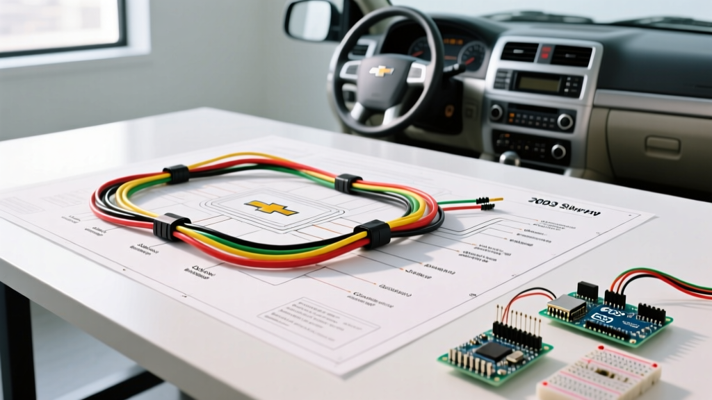

Installation Planning: Wiring Diagram for 2003 Chevy Silverado Radio
Upgrading the head unit in a GMT800 platform truck requires more than just matching wire colors. When consulting a wiring diagram for 2003 Chevy Silverado radio systems, installers frequently encounter the notorious GM Class 2 Data Bus architecture. Unlike older vehicles that use a simple 12V ignition wire to turn the radio on and off, the 2003 Silverado relies on serial data communication to manage power states, OnStar audio routing, and chime retention. Failing to plan for this digital handshake will result in a head unit that either never turns on or parasitically drains your battery within 48 hours.
This installation planning guide provides the exact pinouts, interface requirements, and edge-case troubleshooting necessary for a flawless 2026-era CarPlay or Android Auto upgrade in your 2003 Silverado.
The Split-Year Edge Case: Early vs. Late 2003 Models
Before purchasing any wiring harnesses, you must identify which production run your truck belongs to. The 2003 model year was a transitional period for General Motors, resulting in two entirely different wiring architectures on the assembly line.
- Early 2003 (Non-Bose / Base Audio): Some early-build 1500 models retained the 1999-2002 harness style. These feature a standard 12V switched ignition wire (usually Brown or Pink) at the radio plug. If your factory radio turns on and off with the key without a digital delay, you likely have the older harness and can use a standard GM01 or GM02 hardwire harness.
- Late 2003 & All HD/2500 Models (Class 2 Data Bus): The vast majority of 2003 Silverados, especially those with the Bose Premium Audio package (RPO Y92) or OnStar, use the 24-pin primary and 8-pin secondary connectors. There is no 12V ignition wire in this harness. The radio receives a wake-up signal via the Class 2 Serial Data wire (Pin 12). You must use a CAN-bus/Data-bus interface module.
Pro Tip: Pull the factory radio and look at the connectors. If you see a single large 24-pin block and a smaller 8-pin block next to it, you are dealing with the Class 2 Data Bus system. Plan your hardware budget accordingly.
Essential Hardware & 2026 Interface Pricing
Modern multimedia receivers with wireless Apple CarPlay and Android Auto draw significant standby current. Using a high-quality data-bus interface ensures the truck's Body Control Module (BCM) can properly command the aftermarket radio to sleep. Below is the required hardware matrix for a 2026 installation.
| Component Category | Recommended Part Number | Function & Notes | Est. 2026 Price |
|---|---|---|---|
| Dash Kit | Metra 99-2003 | Double-DIN to Single-DIN stack adapter with pocket. | $18.00 |
| Wiring Interface (Non-Bose) | Axxess XSVI-2105-LAN | Translates Class 2 data to 12V ignition; retains OnStar. | $75.00 |
| Wiring Interface (Bose) | PAC OS2C-BOSE | Retains Bose amplifier turn-on, OnStar, and door chimes. | $65.00 |
| Antenna Adapter | Metra 40-GM10 | Standard GM male to Motorola male antenna adapter. | $12.00 |
| Steering Wheel Control | Axxess ASWC-1 | Retains factory volume/seek buttons (requires separate wiring). | $80.00 |
GM 24-Pin & 8-Pin Connector Pinout Matrix
When bench-wiring your harness adapter to the aftermarket head unit's pigtail, reference this pinout. Always verify with a multimeter, as GM occasionally altered wire colors mid-production. For authoritative installation standards and safety practices, refer to the Crutchfield Car Stereo Installation Guide.
Primary 24-Pin Connector (Speaker & Power)
| Pin | Wire Color | Function | Aftermarket Connection |
|---|---|---|---|
| 1 | Yellow | Constant 12V Battery (+) | Yellow (Memory) |
| 2 | Black | Chassis Ground | Black (Ground) |
| 12 | Light Green/Black | Class 2 Serial Data | Data Interface Module (Do NOT connect to radio) |
| 13 | Tan | Left Front Speaker (+) | White |
| 14 | Gray | Left Front Speaker (-) | White/Black |
| 15 | Brown | Right Front Speaker (+) | Gray |
| 16 | Light Blue | Right Front Speaker (-) | Gray/Black |
| 17 | Green | Left Rear Speaker (+) | Green |
| 18 | Black/White | Left Rear Speaker (-) | Green/Black |
| 19 | Purple | Right Rear Speaker (+) | Violet |
| 20 | Dark Blue | Right Rear Speaker (-) | Violet/Black |
Secondary 8-Pin Connector (Bose / OnStar / Amp)
| Pin | Wire Color | Function |
|---|---|---|
| 1 | Dark Green | Amplifier Right Rear Input (+) |
| 2 | Light Green | Amplifier Left Rear Input (+) |
| 5 | Brown/White | Amplifier Turn-On (Bose Systems) |
Step-by-Step Bench Wiring & Testing Protocol
Never wire an aftermarket harness directly inside the dark cavity of the Silverado's dashboard. Use the following bench-testing workflow to ensure data-bus synchronization before final assembly. You can verify vehicle-specific fitment data via the METRA Electronics Vehicle Fitment Database prior to cutting or crimping.
- Prep the Harness: Strip 1/4 inch of insulation from the adapter harness and the aftermarket radio pigtail. Use heat-shrink butt connectors (18 AWG for speakers, 12 AWG for power/ground). Avoid electrical tape, which degrades in the extreme heat of a truck cabin.
- Interface Integration: Connect the data-bus interface (e.g., PAC OS2C-BOSE) to the vehicle harness plugs. Route the generated 12V ignition (Red) and accessory (Orange) outputs from the interface to the corresponding wires on the aftermarket radio harness.
- Bench Test: Plug the assembled harness into the truck's factory connectors while the dash is still apart. Turn the key to the ACC position. The data interface should click (internal relay), and the head unit should boot within 3-5 seconds.
- Sleep Mode Verification: Turn the key off, remove it, and open the driver's door (this triggers the BCM to shut down the retained accessory power circuit). Wait 60 seconds. Use a multimeter on the head unit's yellow constant 12V wire. Current draw must drop below 2mA. If it remains high, your data interface is failing to read the Class 2 sleep command.
Failure Modes & Advanced Troubleshooting
Parasitic Battery Drain
The most common failure in GMT800 radio installs is a dead battery after a weekend of parking. This occurs when cheap, unbranded CAN-bus adapters fail to interpret the GM UART-based Class 2 data signal (operating at 10.4 kbps). If the adapter misses the "sleep" broadcast from the BCM, it keeps the aftermarket radio's internal amplifier and processor awake. Solution: Only use certified modules from PAC Audio or Axxess. If using a budget interface, wire an inline 5-prong automotive relay triggered by a true ignition source (like the windshield wiper fuse) to physically cut the radio's ground path upon key removal.
OnStar Muting & Door Chime Loss
In 2003 Silverados, the factory radio acts as the speaker output for the BCM's door chimes and the OnStar module's voice prompts. If you bypass the factory radio without a proper retention interface, you will lose your turn-signal click sounds and door-ajar warnings. The PAC OS2C-BOSE solves this by intercepting the OnStar audio lines and mixing them with the aftermarket radio's audio, temporarily muting the music when OnStar or a chime is active.
Steering Wheel Control (SWC) Dropouts
The 2003 Silverado uses a resistive ladder network for steering wheel buttons. If your ASWC-1 module is programmed but the buttons act erratically (e.g., Volume Up triggers Track Skip), the ground reference for the SWC circuit is likely shared with a noisy aftermarket LED dash bulb or a poor chassis ground. Ensure the SWC ground wire is tied directly to a clean, unpainted metal bolt on the dash frame, not daisy-chained to the radio harness ground.
Frequently Asked Questions
Can I use a standard 1999-2002 GM harness on my 2003 Silverado?
Only if you have an early-build, base-model truck without OnStar or Bose. If your truck has a digital clock display on the dash or steering wheel audio controls, you require the Class 2 Data Bus interface. Plugging a standard harness into a Data Bus truck will result in zero power to the new radio.
Do I need to run a new 12V constant wire from the battery?
The factory Yellow wire on the 24-pin connector is fused and capable of handling up to 15 amps, which is sufficient for 95% of modern aftermarket head units. However, if you are installing a high-power unit (like an Alpine or Pioneer with built-in 50W x 4 amplifiers) and a DSP, it is highly recommended to run a dedicated 12 AWG constant 12V wire directly to the battery with an inline 15A fuse to prevent voltage sag and alternator whine.