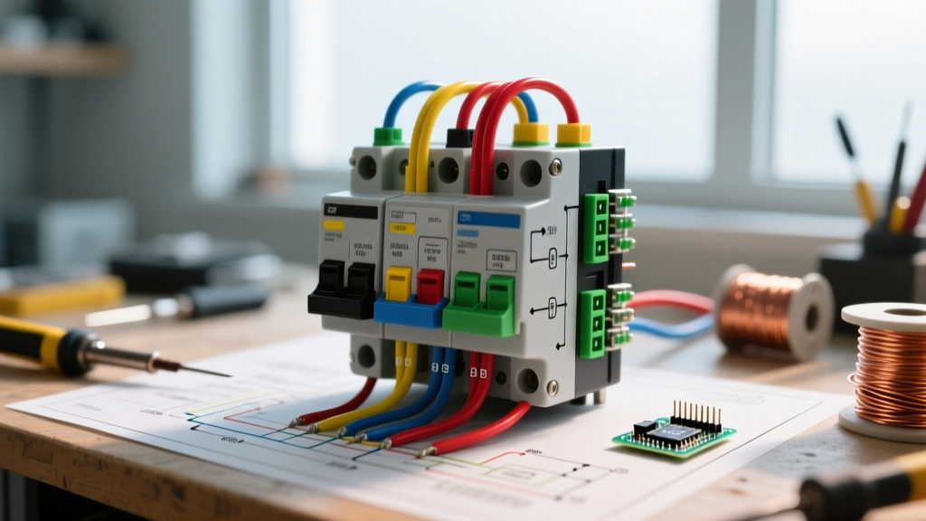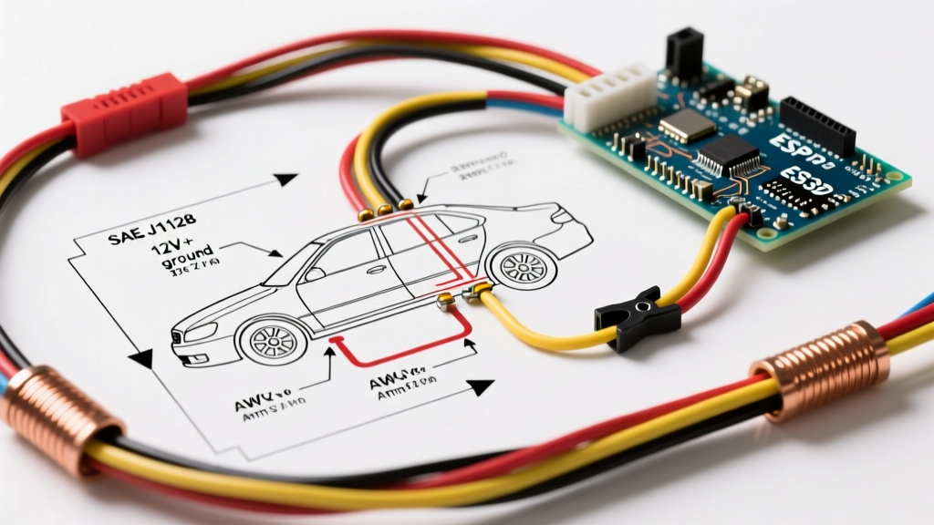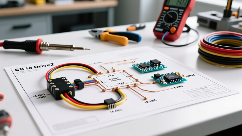

Decoding the Wiring Diagram for Radio Troubleshooting
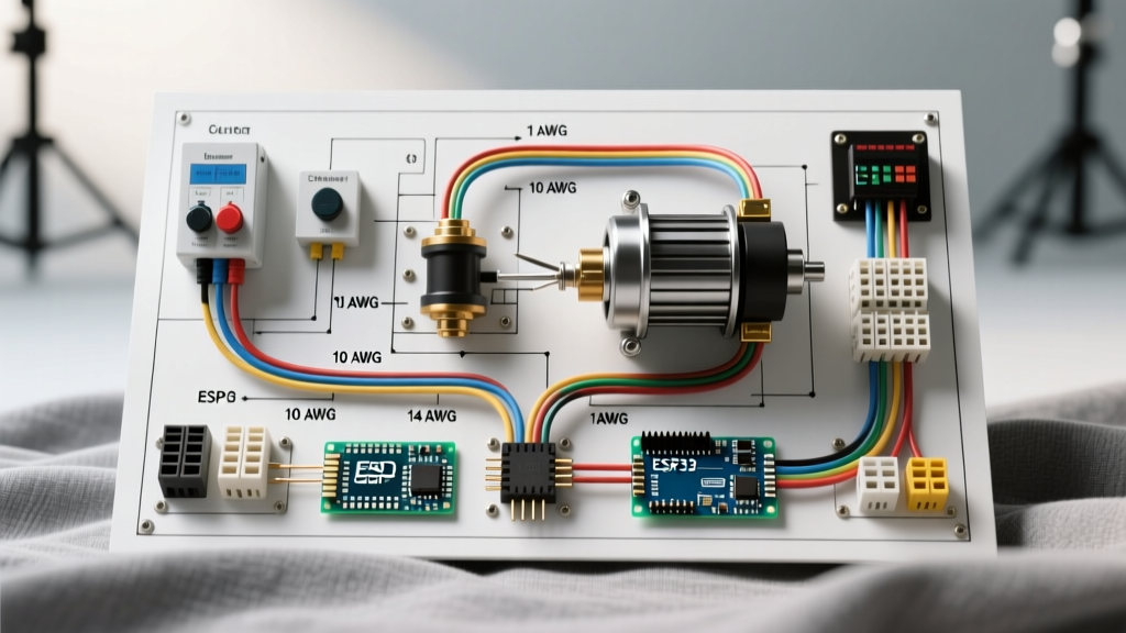
When an aftermarket head unit fails to power on, loses its presets, or emits a high-pitched alternator whine, guessing the root cause is a waste of time and risks frying expensive electronics. A proper wiring diagram for radio troubleshooting is your definitive roadmap. Rather than blindly swapping connections, professional installers use the diagram in tandem with a digital multimeter to isolate voltage drops, ground loops, and data-bus failures.
As of 2026, vehicle electrical architectures have evolved significantly. While the classic EIA/CEA color codes still apply to the head unit's pigtail, modern vehicles rely heavily on CAN-bus and LIN-bus networks. This means a traditional 'switched 12V' red wire is increasingly rare in late-model cars, requiring data interface modules. This guide will walk you through advanced, diagram-based troubleshooting for both legacy and modern CAN-bus vehicle systems.
The Standard EIA/CEA Color Code Matrix
Before troubleshooting, you must verify that the aftermarket radio's pigtail matches the Consumer Technology Association (CTA) standard. If you are using a universal harness adapter, the colors should align perfectly. If they do not, your wiring diagram for radio installation must be adjusted to prevent catastrophic shorts.
| Wire Color | Function | Troubleshooting Target |
|---|---|---|
| Yellow | Constant 12V (Memory) | Verify 12.2V-12.6V with ignition OFF. |
| Red | Switched 12V (Ignition) | Verify 0V (OFF) and 12.2V-14.4V (ON). |
| Black | Chassis Ground | Check for voltage drop (Must be <0.05V). |
| Blue / Blue-White | Power Antenna / Amp Turn-On | Verify 12V only when radio is ON or in Radio mode. |
| Orange | Illumination | Verify 12V when parking lights are ON. |
| White / White-Black | Front Left Speaker (+/-) | Check impedance (should read ~4 ohms). |
| Gray / Gray-Black | Front Right Speaker (+/-) | Check for shorts to chassis ground. |
| Green / Green-Black | Rear Left Speaker (+/-) | Verify polarity with a 9V battery pop test. |
| Purple / Purple-Black | Rear Right Speaker (+/-) | Ensure no shared grounds with other speakers. |
Scenario-Based Troubleshooting Using the Diagram
Scenario 1: The 'Memory Loss' Bug (Yellow vs. Red Swap)
The Symptom: Every time you turn off the car, your radio loses its clock, EQ settings, and Bluetooth pairings.
The Diagram Diagnosis: The wiring diagram for radio memory dictates that the Yellow wire requires unswitched, constant battery voltage, while the Red wire requires ignition-switched voltage. In many European vehicles (like older VWs and Peugeots) and some older Japanese models, the factory harness swaps the constant and switched pins at the ISO 10487 connector.
The Fix: Do not cut and splice the radio's pigtail. Instead, use a multimeter to probe the vehicle's factory harness. Identify the constant 12V pin and the switched 12V pin. Then, use a small flathead screwdriver to depin the Yellow and Red wires at the plastic adapter harness block and swap their positions. This maintains the integrity of the wiring harness while matching the vehicle's specific pinout.
Scenario 2: Alternator Whine and Ground Loop Diagnostics
The Symptom: A high-pitched whine that increases in pitch as you rev the engine, audible through the speakers.
The Diagram Diagnosis: Your wiring diagram shows the Black wire routing to a chassis ground. Alternator whine is almost always a ground loop issue, meaning the radio and the amplifier are grounded at different points with different electrical potentials, causing audio signal interference.
The Fix: According to IPC/WHMA-A-620 wiring harness standards, ground connections must be bare metal to bare metal. Scrape away all paint, primer, and rust from the chassis grounding point. Use a 10 AWG or 12 AWG ring terminal secured with a stainless steel bolt and a star washer. To verify the fix, use your multimeter in DC Voltage mode. Place the black probe on the battery's negative terminal and the red probe on the radio's Black ground wire. With the engine running and the volume up, the voltage drop must read less than 0.05V. If it reads higher, your ground is inadequate.
Scenario 3: Parasitic Draw & CAN-Bus Sleep Failures (2015+ Vehicles)
The Symptom: The radio stays on after you remove the key and open the door, eventually draining the car battery overnight.
The Diagram Diagnosis: In modern 2026 vehicle architectures, the factory radio doesn't use a physical Red switched 12V wire. Instead, it receives a 'wake-up' command via the CAN-bus data lines. If you wired an aftermarket radio using a cheap, generic 'add-a-circuit' fuse tap to the cigarette lighter for switched power, you may be back-feeding voltage into the CAN-bus network, preventing the vehicle's BCM (Body Control Module) from going to sleep.
The Fix: You must use a vehicle-specific data interface module (such as the PAC RP4-FD11 for Ford or the Axxess CRX-CH for Chrysler). These modules read the CAN-bus data and generate a clean, isolated 12V switched output for the radio's Red wire without interfering with the vehicle's sleep cycle.
Multimeter Testing Protocol for Radio Power
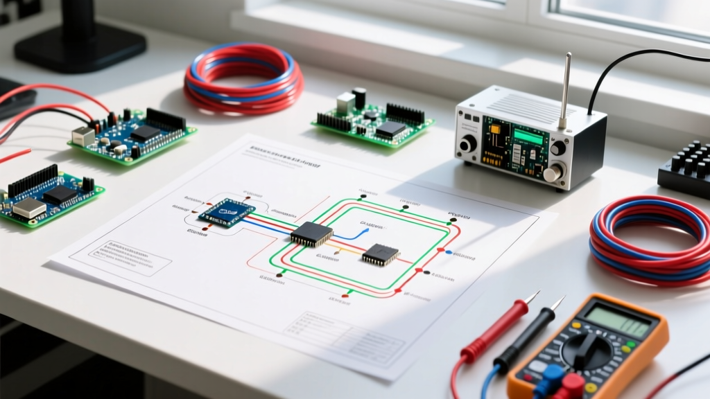
When your wiring diagram for radio installation indicates a power failure, skip the test light. Test lights do not show voltage drops or data-bus anomalies. Use a True-RMS digital multimeter. As outlined in Fluke's guide on measuring DC voltage, proper probing technique is essential to avoid piercing wire insulation, which leads to copper oxidation and future failures.
- Step 1: Set the multimeter to DC Voltage (V⎓).
- Step 2: Insert the black probe into the COM jack and the red probe into the V/Ω jack.
- Step 3: Back-probe the harness connector. Do not pierce the wire insulation with sharp probes; instead, slide the probe tip into the back of the plastic connector where the wire enters.
- Step 4: Test the Yellow wire (Constant). It should read 12.2V to 12.6V with the car off. If it reads below 11.5V, check the inline fuse (usually 10A or 15A ATC/ATO) and the battery health.
- Step 5: Test the Red wire (Switched). It should read 0V with the key off, and jump to 12.2V-14.4V when the ignition is in the 'ACC' or 'ON' position.
Wiring Harness Adapter Compatibility Chart
Never hard-wire an aftermarket radio directly to a vehicle's factory harness. Always use a plug-and-play adapter to preserve resale value and simplify troubleshooting. Below are the industry-standard adapters for common platforms.
| Vehicle Platform | Recommended Adapter | Special Features |
|---|---|---|
| 2001-2020 Honda/Acura | Metra 70-1729 | Standard power, retains factory amp turn-on via Blue wire. |
| 2006-2024 GM (Class 2 Data) | Scosche GM09SR | Includes chime retention and RAP (Retained Accessory Power). |
| 2011-2025 Ford (CAN-bus) | PAC RP4-FD11 | Translates CAN data to 12V switched, retains steering wheel controls. |
| 2008-2023 Toyota (JBL Amp) | Axxess TYTO-01 | Converts high-level factory amp outputs to low-level RCA for aftermarket amps. |
Expert Wiring & Splicing Techniques
If you must extend wires or repair a damaged pigtail, the method you choose dictates the longevity of the installation. The automotive environment is hostile, subject to extreme temperature fluctuations, vibration, and humidity.
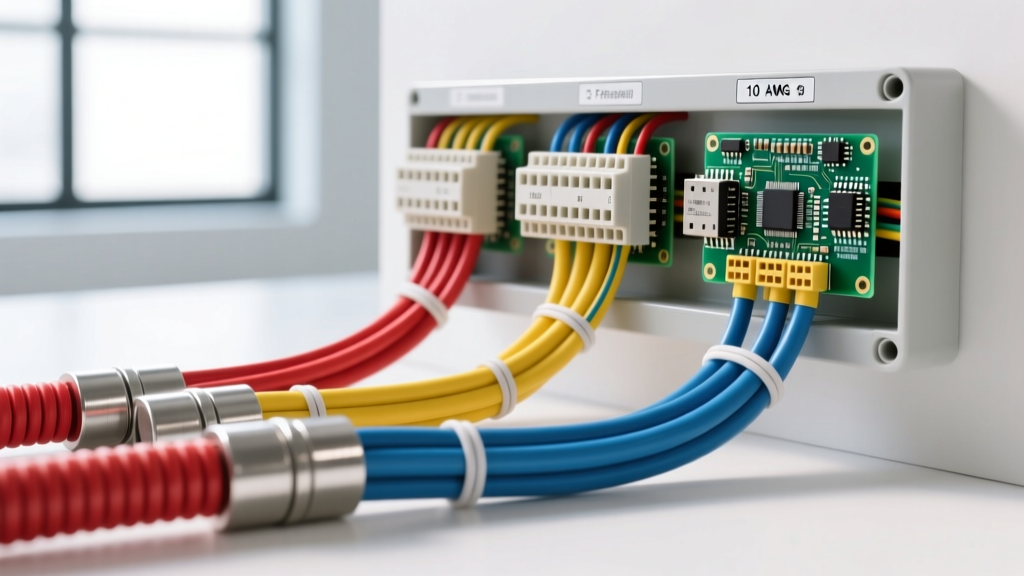
Pro Tip: Abandon standard T-Taps (scotch locks). They cut through the wire strands, reducing the cross-sectional area and inviting corrosion. Instead, use Posi-Tap connectors (e.g., PTV226 for 18-14 AWG) or, ideally, solder the connection using marine-grade adhesive-lined heat shrink tubing (solder sleeves). The adhesive lining melts and seals the splice against moisture ingress.
Frequently Asked Questions (FAQ)
Why does my radio turn on, but there is no sound?
Check the Blue/White wire (Amp Turn-On) on your wiring diagram. If your vehicle has a factory amplifier, this wire must be connected to the amplifier's turn-on trigger. If it is not connected, the radio will power on, but the factory amp will remain in standby mode, producing no sound.
Can I connect the Yellow and Red wires together to a constant 12V source?
Technically, yes, this will power the radio and retain memory. However, the radio will never turn off automatically when you remove the key. You will have to manually power it down every time you exit the vehicle, which is highly impractical and risks battery drain.
What size inline fuse should I use for the head unit?
Most standard aftermarket head units (Pioneer, Kenwood, Alpine) draw between 8A and 12A under normal operating conditions. A 15A ATC/ATO inline fuse on the Yellow constant wire is the industry standard. If you are running high-draw marine radios or units with built-in Class-D amplifiers drawing >15A, upgrade to 12 AWG power wire and a 20A fuse.