
The Anatomy of a 12V Automotive Horn Circuit
Whether you are restoring a classic vehicle, upgrading to high-decibel air horns, or replacing a failed OEM unit, understanding the correct wiring diagram for car horn systems is essential for both safety and reliability. A car horn is a high-current inductive load. When the electromagnetic coil inside the horn engages, it can draw anywhere from 5 amps for a standard single-disc unit to over 30 amps for dual high-output setups like the Hella Supertones or Wolo Bad Boy compressors.
Because of this high current draw, routing the full load through the delicate copper traces of your steering wheel's clock spring (spiral cable) or a standard dashboard toggle switch will result in catastrophic failure, melted insulation, or electrical fires. This is why modern automotive electrical standards, as outlined by SAE International, mandate the use of a relay-based circuit for any horn drawing more than 10 amps.
Direct vs. Relay: Choosing the Right Configuration
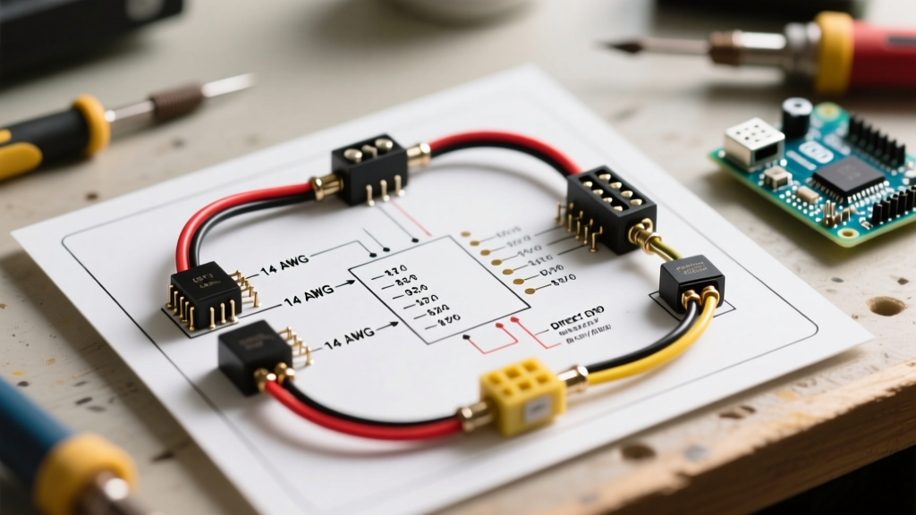
Before pulling wire, you must decide which configuration suits your vehicle. While a direct wiring diagram for car horn setups is simpler, it is largely obsolete for modern applications.
| Feature | Direct Wiring (No Relay) | Relay-Based Wiring (Industry Standard) |
|---|---|---|
| Max Current Capacity | 10 Amps (Limited by switch) | 30 to 40 Amps (Limited by relay contacts) |
| Switch Wear & Tear | High (Arcing degrades contacts) | Minimal (Switch only carries coil current) |
| Voltage Drop | High (Power travels through dash) | Low (Power routed directly from battery) |
| Best Application | Classic cars, low-draw electric horns | Modern vehicles, dual horns, air compressors |
Standard 4-Pin Relay Wiring Diagram for Car Horn (Step-by-Step)
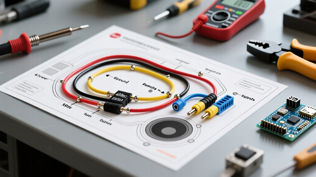
The most reliable and universally accepted wiring diagram for car horn installations utilizes a standard ISO mini 4-pin relay (commonly referred to as a Bosch-style relay, such as the Bosch 0 332 014 150). This setup isolates the high-current load from the low-current control circuit.
Understanding the Ground-Switched Control Circuit
A critical point of confusion for DIY mechanics is how the steering wheel switch interacts with the relay. In 95% of modern vehicles, the horn button on the steering wheel does not send 12V to the relay. Instead, it provides a ground path. The clock spring carries this ground signal down the steering column to the relay coil.
- Pin 30 (Power In): Connect directly to the positive (+) battery terminal via an inline fuse. Use 12 AWG wire for single horns, or 10 AWG for dual high-output horns. The fuse should be rated 125% of the horn's maximum amperage draw (e.g., a 20A horn requires a 25A fuse).
- Pin 87 (Power Out): Connect to the positive (+) terminal on the horn(s). Use the same gauge wire as Pin 30. If running dual horns, use a waterproof split-loom junction block rather than twisting and taping wires at the relay.
- Pin 86 (Coil Power): Connect to an ignition-switched 12V source. This ensures the horn cannot be accidentally drained or triggered when the vehicle is off. Use 16 AWG wire.
- Pin 85 (Coil Ground): Connect to the horn switch output (the clock spring wire). When the driver presses the horn pad, this pin is connected to the chassis ground, completing the relay coil circuit and snapping the internal contacts shut.
Expert Insight: Never rely on the horn's mounting bracket for its primary ground. High-frequency vibrations and road salt rapidly degrade the electrical continuity between the horn chassis and the vehicle frame. Always run a dedicated 12 AWG ground wire from the horn's negative terminal directly to a clean, bare-metal chassis point or the battery negative terminal.
Wire Gauge and Amperage Sizing Chart
Undersized wiring is the leading cause of weak horn output. Voltage drop over long wire runs starves the electromagnetic coil inside the horn, resulting in a pathetic, low-pitched wheeze. Refer to this sizing chart based on the total length of the wire run (positive and negative combined) and the total amperage draw of your specific horn model.
| Total Circuit Length | 10 Amps (Single OEM) | 20 Amps (Dual Standard) | 30+ Amps (Air Compressors) |
|---|---|---|---|
| Under 10 Feet | 16 AWG | 12 AWG | 10 AWG |
| 10 to 20 Feet | 14 AWG | 10 AWG | 8 AWG |
| Over 20 Feet | 12 AWG | 8 AWG | 6 AWG |
Modern Complications: The Clock Spring and CAN Bus
When applying a standard wiring diagram for car horn circuits to vehicles manufactured after 2010, you must account for the clock spring (spiral cable) and Controller Area Network (CAN bus) systems. The clock spring is a coiled ribbon cable inside the steering column that maintains electrical continuity while the wheel turns. According to diagnostic guidelines from AA1Car, the resistance of a healthy clock spring horn circuit should be less than 2 ohms.
If your vehicle uses a multiplexed CAN bus system, the horn button may not be a simple physical switch. Instead, it may be a resistor-ladder switch or a digital input read by the Steering Angle Sensor (SAS) module, which then sends a digital command to the Body Control Module (BCM) to trigger a solid-state relay. Bypassing the BCM to install a traditional 4-pin relay on these vehicles can trigger Check Engine Lights (CEL) or cause the BCM to shut down the circuit entirely to protect against perceived short circuits. Always consult factory service manuals before tapping into modern steering column wiring.
Troubleshooting Matrix: Failure Modes and Edge Cases
Even with a perfect wiring diagram for car horn setups, components fail. Use this diagnostic matrix to isolate the fault without blindly replacing parts.
| Symptom | Probable Cause | Diagnostic Action |
|---|---|---|
| Horn clicks at relay, but no sound | Voltage drop at horn terminals or corroded ground | Measure voltage directly at the horn's positive terminal while the button is pressed. If below 11.5V, repair the wiring or ground. |
| Horn works intermittently | Failing clock spring ribbon cable | Turn the steering wheel lock-to-lock while holding the horn. If it cuts out at specific angles, replace the clock spring. |
| Horn sounds continuously | Stuck relay contacts or shorted horn switch | Disconnect the control wire at Pin 85. If the horn stops, the switch or clock spring is shorted to ground. If it continues, the relay is internally fused and must be replaced. |
| Horn sounds weak or distorted | Internal diaphragm corrosion or low voltage | Bench-test the horn directly on a 12V battery. If it is loud on the bench but weak on the car, you have a severe voltage drop in the vehicle wiring. |
Final Safety and Compliance Notes
When upgrading your horn, ensure the decibel output and frequency comply with local transportation regulations. The National Highway Traffic Safety Administration (NHTSA) and local DOT equivalents mandate that passenger vehicle horns must emit a minimum sound level (typically 93 dB at 7 meters) but restrict the use of multi-tone, siren, or train-horn frequencies on public roadways. Always use marine-grade heat shrink butt connectors and Deutsch-style waterproof connectors for any wiring routed near the radiator or front bumper to prevent moisture ingress and subsequent copper oxidation.