
Understanding the Automatic Transfer Switches for Generators Wiring Diagram
Wiring an Automatic Transfer Switch (ATS) for standard resistive loads like lighting and baseboard heaters is relatively straightforward. However, when your backup power system must handle heavy inductive motor loads—such as HVAC compressors, well pumps, and industrial exhaust fans—the complexity increases exponentially. Motors require massive inrush currents to start, and mismanaging the transfer sequence can destroy compressor windings, trip generator breakers, or cause severe voltage dips.
This motor wiring tutorial breaks down the exact architecture of an automatic transfer switches for generators wiring diagram, focusing specifically on how to integrate motor contactors, manage Locked Rotor Amps (LRA), and comply with the latest 2026 NEC guidelines for standby systems.
Service Entrance vs. Non-Service Entrance ATS Configurations
Before pulling any 2/0 AWG copper wire, you must identify whether your ATS is Service Entrance (SE) rated or Non-Service Entrance (NSE). This dictates where the main disconnect and grounding bond occur.
| Feature | Service Entrance (SE) ATS | Non-Service Entrance (NSE) ATS |
|---|---|---|
| Main Disconnect | Integrated into the ATS (acts as main panel) | Requires upstream main breaker panel |
| Neutral Bonding | Neutral bonded to ground inside the ATS | Neutral bonded at the upstream main panel |
| Typical Use Case | Whole-house backup replacing main panel | Subpanel backup or commercial motor control centers |
| Example Model | Generac RXSW200A3 (~$1,100) | ASCO 300 Series 200A NSE (~$1,850) |
Step-by-Step Motor Load Wiring Sequence
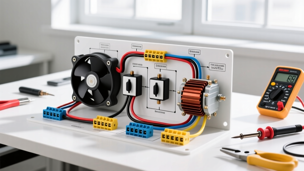
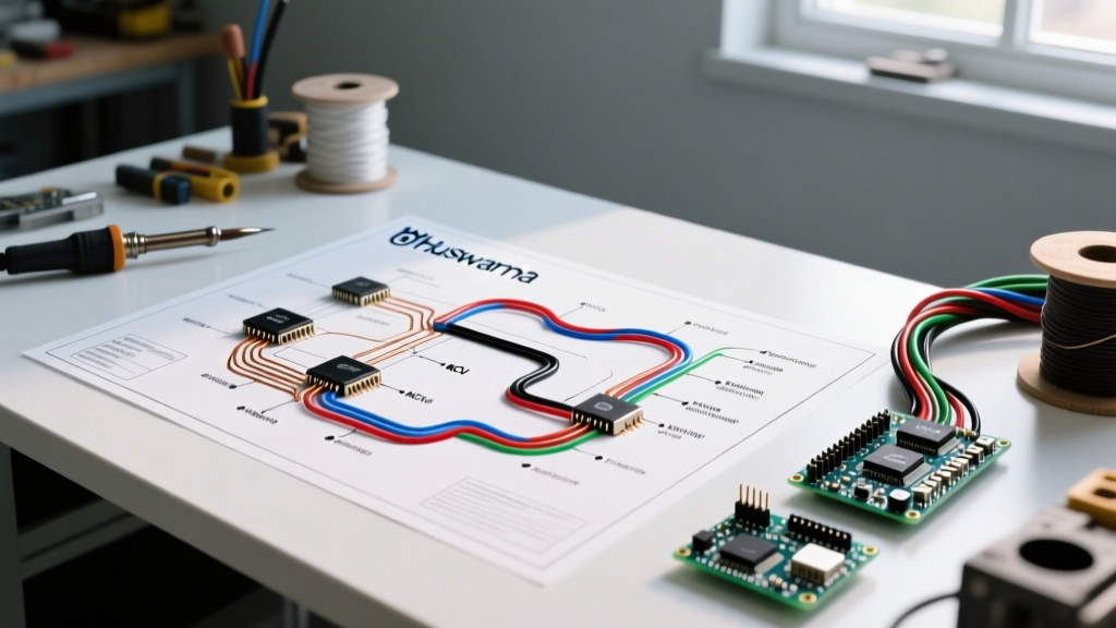
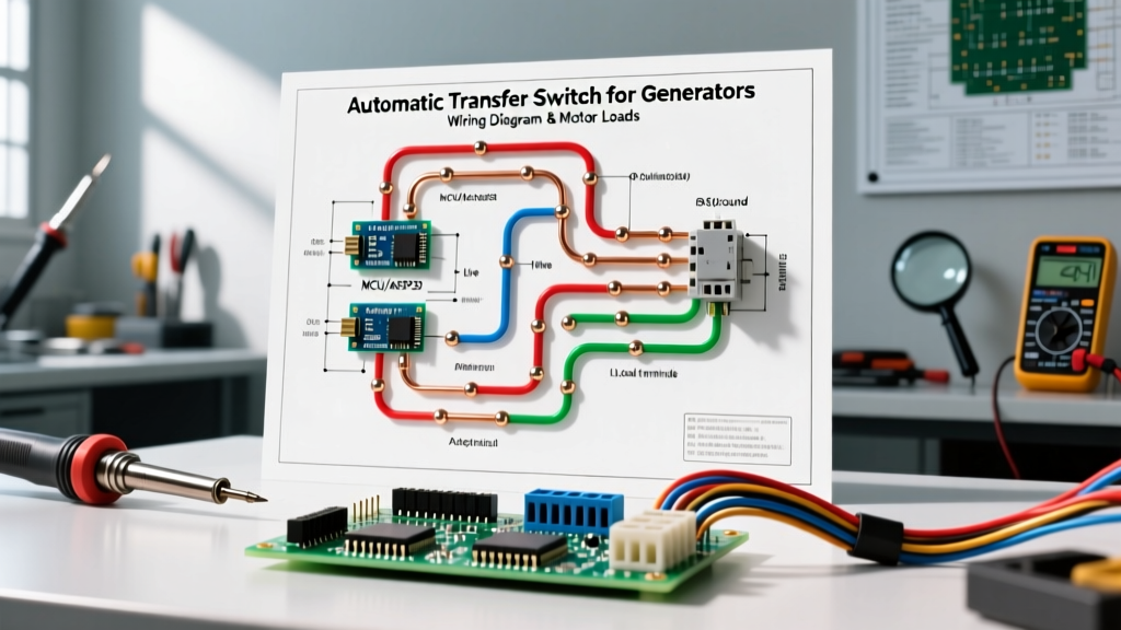
When interpreting your automatic transfer switches for generators wiring diagram, the power wiring is only half the battle. The control circuit logic is what protects your motors during the transition. Here is the standard sequence for a 200A SE-rated ATS feeding a motor-heavy subpanel.
1. Power Conductor Termination
For a 200A system, use 2/0 AWG THHN copper conductors. Route the Utility Source lines to the top lugs (L1, L2) and the Generator Source lines to the emergency lugs (E1, E2). The Load side feeds your motor control center or subpanel. Torque all lugs to the manufacturer's exact specification (typically 250-300 in-lbs for 2/0 wire) to prevent thermal runaway under high motor starting currents.
2. Control Wiring (N1, N2, T1, T2)
The ATS needs to know when the generator is running.
- N1 & N2: Connect these from the generator's control board to the ATS. These 14 AWG wires carry 120V AC to tell the ATS the generator is producing stable power.
- T1 & T2: Connect these from the ATS to the generator's two-wire start contacts. When utility power drops, the ATS closes this circuit, signaling the generator to crank.
3. Grounding and Bonding
According to NEC Article 702 and standard grounding practices, if using an SE ATS, the neutral and ground are bonded inside the ATS enclosure. The generator must be configured as a non-separately derived system (floating neutral) to prevent parallel neutral paths, which can cause nuisance tripping on GFCI/AFCI motor circuits.
The Motor Inrush Problem: Sizing for Locked Rotor Amps (LRA)
The most common point of failure in ATS motor wiring is ignoring the difference between Full Load Amps (FLA) and Locked Rotor Amps (LRA). When a 3-ton HVAC compressor starts, it draws FLA (around 15A) while running, but LRA (up to 95A) for the first 300 milliseconds. If your generator and ATS are not sized or timed correctly, the voltage will sag below 190V, causing the motor contactor to drop out and chatter violently.
| Motor Load Type | Horsepower / Tonnage | Running Amps (FLA) | Starting Amps (LRA) | Required ATS/Gen Logic |
|---|---|---|---|---|
| Central AC Compressor | 3 Ton | 14A - 18A | 85A - 105A | Hard start kit + 3-sec transfer delay |
| Submersible Well Pump | 1.5 HP (230V) | 8A - 10A | 45A - 55A | Time-delay relay on contactor coil |
| Industrial Exhaust Fan | 5 HP (230V 3-Phase) | 15A | 90A | VFD with ride-through capability |
Integrating Time-Delay Contactors for HVAC and Well Pumps
To protect motors from out-of-phase transfers and voltage sags, professional motor wiring tutorials recommend isolating heavy inductive loads using Definite Purpose Contactors (DPCs) wired with time-delay relays.
Pro-Tip: The Out-of-Phase Transfer Danger
If utility power drops while an HVAC compressor is still spinning down, the motor generates back-EMF. If the ATS transfers to the generator immediately, the generator's voltage waveform may be 180 degrees out of phase with the motor's back-EMF. This results in a massive current spike that can weld contactor contacts or snap the compressor crankshaft. Always program a minimum 5-second 'Time Delay on Transfer' in your ATS controller to let the motor's magnetic field collapse.
Wiring the Interposing Time-Delay Relay
For well pumps, wire an interposing time-delay relay (such as the Macromatic TR-60122, approx. $65) between the ATS load side and the motor contactor coil.
- Feed 240V from the ATS load bus to the time-delay relay's power input.
- Set the relay to 'ON-Delay' mode with a 4-second timeout.
- Wire the relay's normally-open (NO) dry contacts in series with the 24V control circuit of the well pump's motor starter.
- When the ATS transfers to generator power, the relay waits 4 seconds for the generator's voltage and frequency to stabilize before energizing the motor contactor.
Smart Load Shedding: Prioritizing Motors During Transfer
If your generator is undersized for the combined LRA of all connected motors, you must implement load shedding. Modern ATS units, like the Generac Smart Management Modules (SMM), use current transformers (CTs) clamped around the motor feeder wires. If the ATS detects the generator frequency dropping below 58Hz during motor startup, it automatically sheds non-essential loads (like water heaters) to reserve cranking amps for the priority motor.
For commercial applications governed by NFPA 110 Level 1 standards, load shedding must be hardwired via under-frequency relays that physically drop the coils of non-essential motor starters within milliseconds of a frequency dip.
Common Failure Modes and Troubleshooting
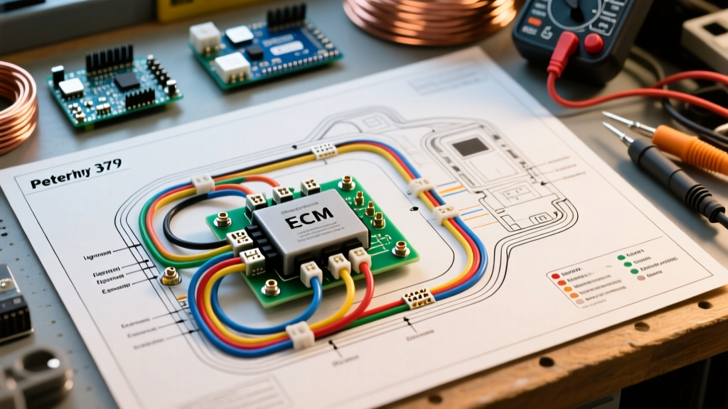
Even with a perfect automatic transfer switches for generators wiring diagram, field conditions can introduce faults. Here is how to troubleshoot motor-specific ATS issues:
- Contactor Chattering: The motor contactor rapidly clicks on and off during transfer. Cause: Generator voltage sag dropping below the contactor's minimum holding voltage (usually 85% of nominal). Fix: Install a soft-start device on the motor or upgrade the generator's alternator to a higher inertia model.
- ATS Fails to Retransfer to Utility: The generator runs indefinitely despite utility power returning. Cause: The utility sensing wires (often connected to the load side of the main breaker) are reading 'ghost voltage' generated by the motor's back-EMF feeding back through the ATS. Fix: Ensure utility sensing is wired directly to the utility source lugs, not the load bus.
- Nuisance GFCI Tripping on Motor Circuits: Cause: Improper neutral-to-ground bonding creating parallel neutral paths during the transfer transient. Fix: Verify the generator neutral is floating and the ATS SE bonding screw is correctly installed.
Frequently Asked Questions
Can I wire a 3-phase motor to a single-phase ATS?
No. A standard residential single-phase ATS cannot natively start a 3-phase motor. You must use a rotary phase converter or a Variable Frequency Drive (VFD) wired on the load side of the ATS to generate the third leg. The VFD must be sized at least 1.5x the motor's FLA to handle the single-phase input rectification.
What wire gauge is required for the ATS control circuit?
For N1/N2 and T1/T2 control wires, 14 AWG stranded copper is standard for runs under 50 feet. If the generator is located more than 100 feet from the ATS, step up to 12 AWG to prevent voltage drop across the start contacts, which can cause the generator's logic board to misread the ATS state.
Do I need a bypass isolation ATS for critical motor loads?
For life-safety motor loads (e.g., hospital ventilation, fire pumps), a Bypass Isolation ATS is required. This allows you to manually bypass the automatic switch and draw power directly from the utility or generator while the primary ATS is removed for maintenance, ensuring zero downtime for critical motor infrastructure.