
Understanding the Core: 18 AWG vs. 20 AWG Thermostat Wire
When evaluating a wiring diagram for AC thermostat setups, the physical properties of the cable are just as critical as the terminal mappings. HVAC control circuits operate as Class 2 low-voltage systems, typically supplying 24VAC from the air handler's step-down transformer. According to the National Fire Protection Association (NFPA) NEC Article 725, Class 2 circuits have specific power and wiring limitations to prevent fire hazards.
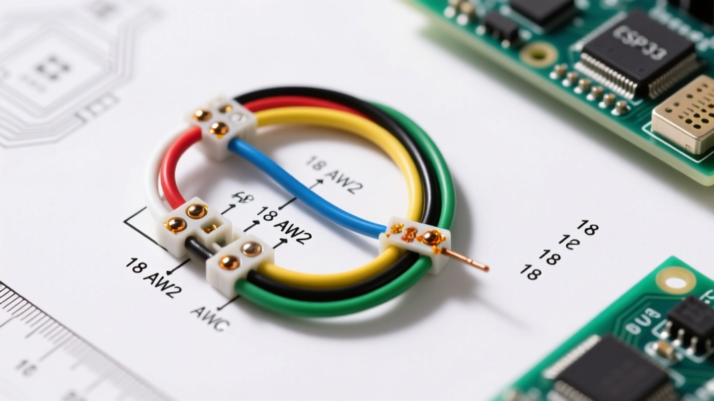
The undisputed industry standard for thermostat wiring is 18 AWG solid copper wire. While you may occasionally find 20 AWG wire in older or budget-conscious installations, using anything smaller than 18 AWG introduces significant voltage drop risks over longer runs. Modern smart thermostats, such as the Nest Learning Thermostat 4th Gen or the Ecobee Smart Thermostat Premium, require a stable voltage supply (typically between 20VAC and 30VAC) to power their Wi-Fi radios, backlit displays, and occupancy sensors.
The Physics of Voltage Drop in Thermostat Wiring
An 18 AWG solid copper wire has a resistance of approximately 6.38 ohms per 1,000 feet. If your thermostat is located 50 feet from the air handler (meaning a 100-foot total loop for the circuit), and the smart thermostat draws a peak current of 1.5 Amps during Wi-Fi transmission, the voltage drop calculates to roughly 0.95V. This leaves 23.05V at the thermostat baseplate—well within the safe operating range. If you substitute 22 AWG telephone wire (a common DIY mistake), the resistance jumps to 16.14 ohms per 1,000 feet, causing a voltage drop of 2.42V, which can trigger reboot loops or blow the control board's 3A ATC fuse during compressor staging.
Pro-Tip: Always use solid core 18 AWG wire rather than stranded wire for HVAC terminals. The screw-down terminal blocks on standard HVAC control boards and thermostat baseplates are engineered to clamp down on solid wire. Stranded wire can fray, causing loose connections, arcing, or accidental short circuits between adjacent terminals.
The Definitive Thermostat Wire Color Code Matrix
Standard thermostat cables are manufactured with a specific color-coded jacket to ensure uniformity across the HVAC industry. However, older homes or previous DIY repairs may feature non-standard colors. Always verify the function with a multimeter rather than trusting the jacket color blindly. Below is the universal color code reference for standard 5-wire and 8-wire configurations.
| Terminal | Standard Color | Alternate Color | Function | Voltage / State |
|---|---|---|---|---|
| R / Rc / Rh | Red | N/A | 24VAC Power Source | Constant 24VAC |
| C | Blue | Black / Brown | Common (Completes 24VAC Circuit) | 0V (Return Path) |
| W / W1 | White | N/A | Primary Heat (Gas/Oil/Electric) | 24VAC when calling for heat |
| Y / Y1 | Yellow | N/A | Primary Cooling (Compressor) | 24VAC when calling for cool |
| G | Green | N/A | Indoor Blower Fan | 24VAC when fan is ON |
| O / B | Orange (O) / Dark Blue (B) | N/A | Reversing Valve (Heat Pumps Only) | 24VAC (O=Cool, B=Heat) |
| W2 / E | Pink / Brown | White (Striped) | Auxiliary / Emergency Heat | 24VAC (Aux/Emergency stages) |
| Y2 | Light Blue | Yellow (Striped) | Second Stage Cooling | 24VAC (Stage 2 cool call) |
Decoding the Wiring Diagram for AC Thermostat Systems
Interpreting a wiring diagram for AC thermostat systems requires understanding the logical flow of the 24VAC control circuit. The transformer inside your air handler or furnace has two secondary terminals: one provides 24VAC (connected to the R terminal), and the other provides the return path or Common (connected to the C terminal).
When the thermostat's internal relay closes for a cooling call, it bridges the R and Y terminals. This sends 24VAC down the Yellow wire to the air handler's control board, which then energizes the contactor coil for the outdoor condenser unit. Simultaneously, the thermostat bridges R and G to turn on the indoor blower fan.
Heat Pump Specifics: The O/B Terminal Logic
If your wiring diagram includes a heat pump, you must pay special attention to the reversing valve terminal. Most manufacturers (like Trane, Carrier, and Lennox) default to the O terminal, which energizes the reversing valve during a cooling call. However, Rheem and Ruud systems typically use the B terminal, energizing the valve during a heating call. Wiring this incorrectly won't damage the system, but it will invert your heating and cooling modes—a highly common edge case that confuses DIY installers.
The C-Wire Conundrum: Power Stealing vs. Dedicated Common
As of 2026, the ENERGY STAR Smart Thermostat Specifications heavily favor dedicated C-wire connections. Early smart thermostats relied on "power stealing," a technique where the device leaks a tiny amount of current (usually under 20mA) through the Y or W circuit to charge its internal battery without completing the circuit and turning on the HVAC equipment.
Power stealing is notoriously unreliable. It can cause ghost-flashing of LED indicators on modern gas valves, prevent the AC compressor from fully disengaging, or cause the thermostat to drop Wi-Fi connectivity during the off-season when neither heating nor cooling is actively cycling. If your existing wall cable lacks a C-wire, you have two actionable solutions:
- Pull a New 18/5 Cable: Replace the old 4-wire cable with a standard 18/5 (5-conductor) thermostat wire, utilizing the unused Blue or Black wire for the C terminal at both the control board and the thermostat baseplate.
- Install a C-Wire Adapter (Add-A-Wire): If pulling new wire through finished drywall is impossible, use a 24VAC C-wire adapter kit (like the ecobee Power Extender Kit). This device multiplexes the power and signal over the existing wires at the furnace board and demultiplexes them behind the thermostat.
Critical Failure Modes and Edge Cases
Even with a perfect wiring diagram for AC thermostat mapping, physical installation errors can lead to catastrophic component failure. Be aware of these specific failure modes:
- Blown 3A ATC Blade Fuse: Located on the main HVAC control board, this fuse protects the 24VAC transformer. If you allow the bare copper ends of the R (Red) and C (Blue) wires to touch while the power is on, you create a dead short. The 3A fuse will blow instantly. Always turn off the breaker to the air handler before stripping or manipulating thermostat wires.
- Frayed Stranded Wire Shorts: As mentioned, using stranded wire can result in a single copper strand escaping the terminal block and touching the adjacent terminal. An R-to-Y short will cause the AC compressor to run continuously, 24/7, regardless of the thermostat settings, potentially freezing the evaporator coil and destroying the compressor.
- Ghost Voltage on Unused Wires: In long cable runs (over 75 feet), unused wires in the thermostat bundle can pick up inductive "ghost voltage" from the live 24VAC wires running parallel to them. While usually harmless, this can sometimes confuse highly sensitive smart thermostat diagnostic circuits. Cap off unused wires with wire nuts at both ends.
Step-by-Step Verification Protocol
Before snapping your new smart thermostat onto its baseplate, follow this verification protocol recommended by the U.S. Department of Energy to ensure your wiring is safe and functional:
- Kill the Power: Turn off the dedicated 120V/240V breaker for your air handler/furnace at the main electrical panel.
- Verify the Transformer: Locate the 24VAC transformer on the control board. Ensure the R wire is connected to the "HOT" or "24VAC" side, and the C wire is connected to the "COM" or "C" side.
- Strip and Seat: Strip exactly 1/4 inch of insulation from your 18 AWG solid wires. Insert them into the baseplate terminals and pull gently to ensure a mechanical bite.
- Multimeter Test: Turn the breaker back on. Set your multimeter to AC Voltage. Place the probes on the R and C terminals at the baseplate. You should read between 24VAC and 28VAC. If you read 0V, check the 3A fuse on the control board.
- Final Mount: Once voltage is confirmed, turn the power back off, mount the thermostat, and restore power to boot up the system.
Frequently Asked Questions
Can I use 16 AWG wire instead of 18 AWG for a thermostat?
Yes, 16 AWG is perfectly safe and actually preferred for exceptionally long runs exceeding 100 feet, as its lower resistance (4.01 ohms per 1,000 ft) minimizes voltage drop. However, 16 AWG is physically thicker and may not fit cleanly into the small terminal blocks of some modern smart thermostat baseplates.
What happens if I wire the G (Fan) and Y (Cooling) terminals backward?
If you swap G and Y, calling for cooling will only turn on the indoor blower fan without engaging the outdoor compressor. Conversely, calling for "Fan Only" will engage the outdoor compressor without the indoor blower, which will rapidly cause the evaporator coil to freeze into a solid block of ice and potentially lead to liquid slugging in the compressor.
Do I need a C-wire if my current analog thermostat works fine without one?
Analog and basic programmable thermostats use micro-amp power stealing or AA batteries, so they don't require a C-wire. However, modern Wi-Fi enabled smart thermostats draw significantly more current. While some claim to operate without a C-wire, relying on power stealing often results in dropped network connections, delayed cooling responses, and premature wear on your HVAC control board relays. Running a dedicated C-wire is always the recommended best practice.