
Understanding the Wiring Diagram for Boat Lift Motor Systems
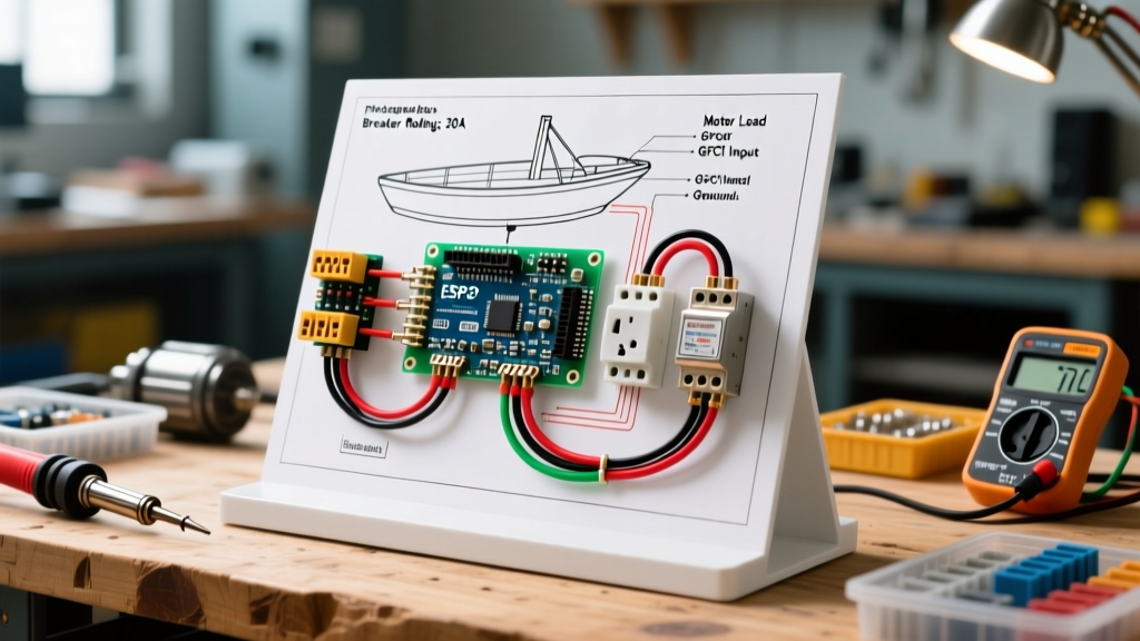
Wiring a boat lift motor requires a precise understanding of single-phase induction motor schematics, marine environmental hazards, and strict National Electrical Code (NEC) compliance. Unlike standard household appliances, a boat lift motor operates in a high-humidity, corrosive environment where stray current and voltage drop can lead to catastrophic failure or severe shock hazards. This guide provides a comprehensive wiring diagram for boat lift motor configurations, focusing on the critical path from the main breaker panel to the motor terminal box.
Most residential boat lifts (such as those from ShoreStation, Hewitt, or Lift-Davit) utilize 1 HP or 1.5 HP capacitor-start/capacitor-run (CSCR) or split-phase single-phase motors. The wiring diagram for boat lift motor systems centers around the NEMA standard terminal board, typically featuring leads labeled T1 through T8, alongside start and run capacitor connections. Properly mapping these terminals to your breaker panel ensures optimal starting torque and prevents the centrifugal switch from failing to disengage.
NEMA Terminal Mapping and Internal Schematic
Before pulling wire through your conduit, you must configure the motor's internal voltage jumpers. Boat lift motors are typically dual-voltage (120V/240V). While 120V is common for shorter dock runs, 240V is highly recommended for runs exceeding 50 feet to mitigate voltage drop and reduce the required wire gauge.
120V Configuration (Standard for <50ft Runs)
- Line 1 (Hot): Connect to T1, T3, and T8.
- Line 2 (Neutral): Connect to T2, T4, and T5.
- Ground: Connect to the green grounding screw on the motor casing.
240V Configuration (Recommended for >50ft Runs)
- Line 1 (Hot A): Connect to T1 and T8.
- Line 2 (Hot B): Connect to T4 and T5.
- Neutral Jumper: Connect T2 and T3 together (insulated wire nut).
- Ground: Connect to the green grounding screw.
Expert Insight: Never rely on the factory jumper settings. Manufacturers frequently ship motors wired for 240V to accommodate commercial applications. Always verify the terminal connections against the schematic glued inside the motor's terminal box cover before energizing the circuit.
Breaker Panel Sizing & Wire Gauge Selection Matrix
Selecting the correct breaker and wire gauge is a function of the motor's Full Load Amps (FLA), the National Electrical Code (NEC) Article 430 requirements for motor circuits, and the physical distance from the panel. Motor circuits require breakers sized to handle the Locked Rotor Amperage (LRA) inrush current without nuisance tripping, while the wire must be sized for the FLA and voltage drop.
| Motor HP | Voltage | Approx. FLA | Min Wire Gauge (Up to 50ft) | Min Wire Gauge (50-100ft) | Breaker Size (GFCI) |
|---|---|---|---|---|---|
| 1.0 HP | 120V | 12.0A | 10 AWG THHN | 8 AWG THHN | 20A Single-Pole |
| 1.5 HP | 120V | 16.0A | 8 AWG THHN | 6 AWG THHN | 30A Single-Pole |
| 1.0 HP | 240V | 6.0A | 14 AWG THHN | 12 AWG THHN | 15A Double-Pole |
| 1.5 HP | 240V | 8.0A | 12 AWG THHN | 10 AWG THHN | 20A Double-Pole |
Note: Wire sizes assume copper conductors in a wet/damp location. For marine environments, we strongly recommend upgrading to tinned marine-grade copper wire (e.g., Ancor or West Marine brands) for the final whip connection to resist galvanic corrosion.
Step-by-Step Breaker Panel to Motor Wiring Procedure
Step 1: Install the GFCI Breaker in the Subpanel
As of the latest NEC updates and continuing into 2026, GFCI (Ground Fault Circuit Interrupter) protection is strictly mandated for all 120V and 240V single-phase marine equipment operating in damp or wet locations. Install a high-quality marine-rated or standard GFCI breaker, such as the Square D QO120GFI (approx. $110-$140) or the Siemens Q220GFI for 240V setups. Connect the pigtail to the panel's neutral bar and route the hot/neutral conductors to the breaker terminals.
Step 2: Route Schedule 80 PVC Conduit
Standard Schedule 40 PVC becomes brittle under prolonged UV exposure and physical impact on a dock. Use Schedule 80 PVC (minimum 3/4-inch diameter) for all exposed runs along the dock and hoist beam. Secure the conduit with stainless steel (316-grade) strut clamps every 3 feet to prevent wind-induced vibration fatigue.
Step 3: Pull Conductors and Manage Voltage Drop
Pull your THHN-2 conductors through the conduit. Use Black (Hot), White (Neutral), and Green (Ground) for 120V; or Black (Hot A), Red (Hot B), White (Neutral, if required by control box), and Green (Ground) for 240V. If your run exceeds 80 feet, calculate voltage drop using the formula: VD = (2 x K x I x L) / CM. Keep voltage drop under 3% to ensure the motor's start capacitor receives adequate voltage to engage the centrifugal switch.
Step 4: Terminate at the Motor Enclosure
Use a watertight NEMA 4X cord grip fitting where the conduit meets the motor terminal box. This prevents moisture ingress and dock spray from shorting the terminals. Apply a dab of OX-Gard or Noalox antioxidant paste to the terminal screws before torquing them down to prevent aluminum/copper oxidation, even when using tinned wire.
Grounding, GFCI Protection, and NEC Compliance
Grounding a boat lift is not just about tripping a breaker; it is about preventing stray current corrosion and protecting human life. According to NFPA's National Electrical Code (NEC) Article 555, which governs Marinas and Boatyards, all electrical equipment installed on docks must be connected to an equipment grounding conductor (EGC). Furthermore, the American Boat and Yacht Council (ABYC) standards emphasize that grounding paths must never rely on the water or the dock's structural metal.
- Equipment Grounding Conductor (EGC): Must be an insulated green wire run all the way back to the main service panel's ground bus. Do not rely on the conduit as a ground path in marine environments.
- Equipotential Bonding: If your boat lift features a metal winch housing, dock frame, or aluminum boat cradle, these non-current-carrying metal parts must be bonded together using a minimum 8 AWG solid copper bonding jumper to eliminate potential differences.
- Grounding Electrode: While the EGC clears faults, driving an independent 8-foot copper-clad ground rod near the dock and bonding it to the lift frame provides an extra layer of lightning and surge dissipation, a practice highly recommended by BoatUS marine electrical experts.
Advanced Troubleshooting: Capacitor and Centrifugal Switch Failures
Even with a perfect wiring diagram for boat lift motor installations, environmental factors cause specific failure modes. Here is how to diagnose the most common issues:
The Motor Hums but Will Not Turn
Diagnosis: Failed start capacitor or stuck centrifugal switch.
Action: Disconnect power and discharge the capacitor using a 20k-ohm, 5-watt resistor. Remove the capacitor and test it with a multimeter capable of reading microfarads (µF). A 1 HP motor typically uses a 100-130 µF start capacitor. If the reading is more than 10% below the rated µF, replace it. If the capacitor tests fine, manually spin the motor shaft; if it feels gritty, the centrifugal switch contacts are corroded and require cleaning with electrical contact cleaner.
GFCI Breaker Trips Instantly Upon Energizing
Diagnosis: Water ingress in the terminal box, degraded winding insulation, or a shared neutral fault.
Action: Inspect the NEMA 4X terminal box for condensation or salt crust. Megger test the motor windings (using a megohmmeter at 500V DC) to check for insulation breakdown to the motor casing. Any reading below 2 Megohms indicates the motor windings are compromised by moisture and the motor must be replaced or professionally rewound.
Motor Overheats and Shuts Down on Thermal Overload
Diagnosis: Severe voltage drop or mechanical binding in the winch gearbox.
Action: Measure the voltage at the motor terminals while the motor is under load (lifting the boat). If a 120V motor is receiving less than 108V (a 10% drop), the run capacitor will overheat, and the thermal overload switch will trip. Upgrade the wire gauge or switch the motor to a 240V configuration to halve the amperage and eliminate the voltage drop.
Frequently Asked Questions
Can I use a standard household receptacle and plug for my boat lift?
No. The NEC strictly prohibits standard receptacles for permanent marine hoist equipment due to the high risk of GFCI failure from corrosion and the danger of a plug disconnecting while under load. The motor must be hardwired through a watertight junction box or directly into the motor terminal enclosure.
Do I need a separate disconnect switch at the dock?
Yes. NEC Article 555.19 requires a readily accessible disconnect switch within sight of the boat lift motor. A NEMA 3R or 4X weatherproof disconnect enclosure housing a manual pull-out block or rotary switch is required for safe maintenance and emergency shutoffs.
Is it safe to use aluminum wire for long dock runs?
While aluminum (like 2-2-2-4 URD) is cost-effective for long underground trench runs to the dock subpanel, it should never be used for the final branch circuit wiring to the boat lift motor. The dissimilar metals (aluminum wire to copper motor terminals) will cause rapid galvanic corrosion in a marine environment, leading to high-resistance hotspots and fire hazards.