
Why 12V DC Requires a Specialized Approach
When adapting a residential comfort feature to a mobile platform, the standard wiring diagram for ceiling fan light installations must be completely reimagined. Unlike 120V AC residential systems where a 14 AWG wire can run 50 feet with negligible loss, 12V DC systems in RVs, camper vans, and motorhomes are hyper-sensitive to voltage drop, inrush currents, and ground loop interference. Installing a 12V DC brushless ceiling fan with an integrated LED light kit requires strict adherence to mobile electrical standards to prevent dimming lights, motor whine, or catastrophic wire overheating.
In this comprehensive vehicle-specific guide, we break down the exact schematic logic, wire gauge mathematics, and component selection required to wire a 12V ceiling fan and light kit safely in an RV or camper van build. Whether you are retrofitting a Class B van or upgrading a fifth-wheel, this guide ensures your installation meets the rigorous demands of mobile DC power systems.
Hardware Bill of Materials (BOM) for Mobile DC Systems
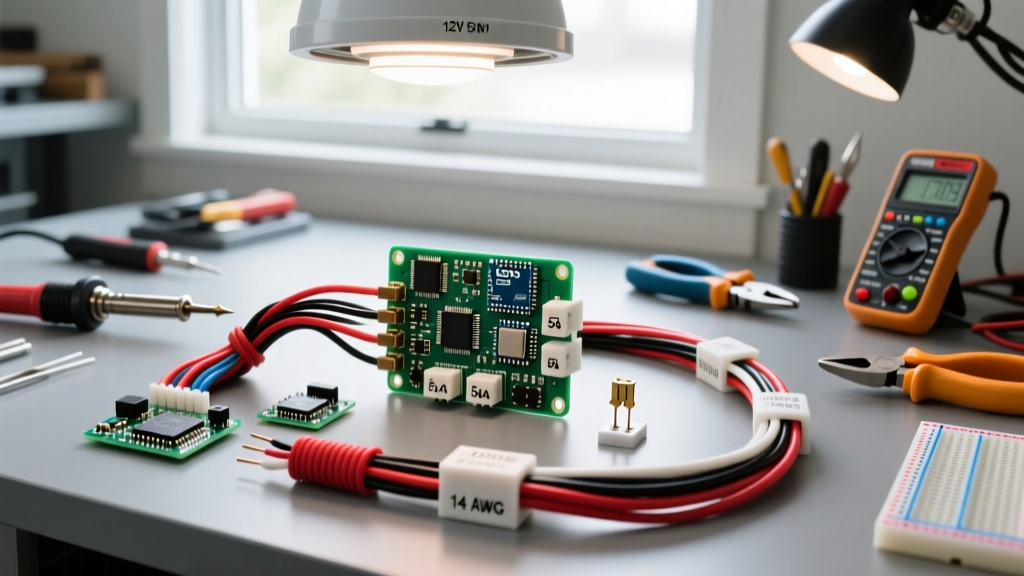
Do not use residential AC components or standard automotive wire for an RV ceiling fan. The vibration of a vehicle requires marine-grade tinned copper wire to prevent oxidation and strand breakage. Below is the exact hardware specification required for a reliable 12V fan and light installation.
| Component | Specification / Model | Purpose & Technical Note |
|---|---|---|
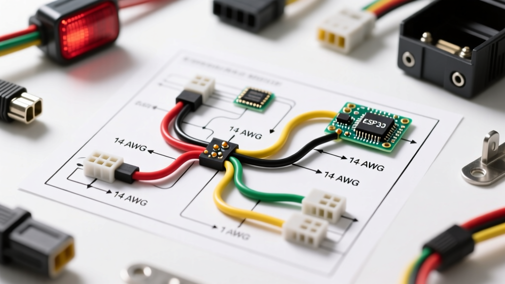
| Primary Wire | Ancor 14 AWG Tinned Marine Wire | Handles fan inrush and continuous draw; tinning prevents corrosion in high-humidity RV environments. |
| Light Circuit Wire | Ancor 16 AWG Tinned Marine Wire | Sufficient for low-draw LED light kits (typically under 0.5A). |
| Fan Fuse | Bussmann 10A ATO Blade Fuse | Protects against shorts; 10A rating accommodates the 50ms inrush spike of brushless DC motors. |
| Light Fuse | Bussmann 5A ATO Blade Fuse | Protects the low-current LED circuit from overcurrent events. |
| Switches | Carling V-Series SPST Rocker | Two separate switches allow independent control of the fan motor and the LED light. |
| Terminals | Ancor Adhesive-Lined Heat Shrink | Creates a waterproof, vibration-proof seal at the fan housing and fuse block connections. |
Wire Gauge Selection and Voltage Drop Mathematics
The most common failure point in RV 12V ceiling fan installations is excessive voltage drop. If the voltage at the fan motor drops below 11.2V, the brushless controller may fail to start the motor, resulting in a clicking sound or complete failure. Furthermore, if the LED light shares a compromised ground or undersized wire, it will flicker as the fan motor cycles.
According to mobile electrical best practices aligned with the American Boat & Yacht Council (ABYC) standards, DC circuits should maintain a voltage drop of less than 3% for critical loads and less than 10% for non-critical lighting. For a 12V system, a 3% drop equates to a maximum loss of 0.36V.
Voltage Drop Calculation Scenario
Assume your ceiling fan draws a continuous 2.5A, and the one-way wire run from the DC fuse block to the ceiling fan housing is 15 feet. Using 14 AWG wire (which has a resistance of approximately 2.525 ohms per 1,000 feet), the math is as follows:
- Formula: Voltage Drop = (2 x Length x Current x Resistance) / 1000
- Calculation: (2 x 15 ft x 2.5A x 2.525) / 1000 = 0.189V Drop
- Percentage: (0.189V / 12V) x 100 = 1.57% Drop
A 1.57% drop is well within the safe 3% threshold, confirming that 14 AWG is the correct choice for the main fan power feed. If your run exceeds 25 feet, you must step up to 12 AWG wire to compensate for the increased resistance.
Step-by-Step Wiring Diagram Logic
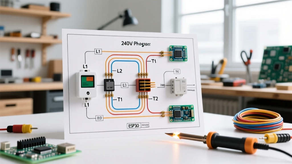
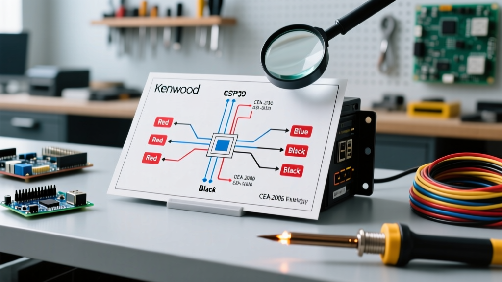
Because we are dealing with a dual-function unit (fan motor + LED light), the wiring diagram must split the power feed after the main distribution block to allow independent switching. Below is the node-to-node routing for the 12V RV ceiling fan light setup.
Phase 1: Power Distribution and Fusing
- Main Feed: Run a 10 AWG positive and negative cable from your primary house battery bank to a Blue Sea ST Blade fuse block mounted centrally in the RV.
- Fan Circuit Fuse: Insert a 10A ATO fuse into slot 1 of the fuse block. This protects the high-draw fan motor.
- Light Circuit Fuse: Insert a 5A ATO fuse into slot 2 of the fuse block. This protects the integrated LED light.
Phase 2: Switch Routing and Independent Control
To ensure the light does not turn on every time you activate the fan, we route the fused power through two separate Carling SPST rocker switches mounted on your interior wall panel.
- Fan Switch: Run 14 AWG wire from the 10A fuse output to the bottom terminal of Switch A. Run another 14 AWG wire from the top terminal of Switch A up through the RV wall cavity to the fan housing.
- Light Switch: Run 16 AWG wire from the 5A fuse output to the bottom terminal of Switch B. Run 16 AWG wire from the top terminal of Switch B to the LED light kit pigtail in the fan housing.
Phase 3: The Ceiling Fan Housing Connections
Inside the fan canopy, you will typically find four wires: Motor Positive (Red), Motor Negative (Black), Light Positive (Blue), and Light Negative (White).
- Connect the 14 AWG positive from Switch A to the Motor Positive (Red).
- Connect the 16 AWG positive from Switch B to the Light Positive (Blue).
- Critical Grounding Step: Splice the Motor Negative (Black) and Light Negative (White) together using a sealed heat-shrink butt connector. From this splice, run a single 14 AWG ground wire down to the main negative bus bar on your fuse block. Never ground the fan motor to the RV metal chassis or ceiling ribs; this creates ground loops that cause LED flickering.
Expert Insight: Always use a ratcheting crimper for your heat-shrink terminals. A loose crimp on a 12V DC motor circuit will create micro-arcing as the vehicle drives down the highway, generating excessive heat that can melt the wire insulation and cause a DC fire.
Troubleshooting Edge Cases in Mobile Environments
Even with a perfect schematic, the harsh environment of a moving vehicle can introduce electrical anomalies. Here is how to diagnose and fix the three most common issues encountered with 12V RV ceiling fan light installations.
1. LED Light Flickering at Low Fan Speeds
The Cause: Most 12V DC fans use Pulse Width Modulation (PWM) controllers to manage speed. At low speeds, the PWM controller rapidly cycles the power on and off. This high-frequency switching can inject electrical noise back into the shared DC ground, causing the sensitive LED light driver to flicker.
The Fix: If you experience this, install a 12V DC inline filter capacitor on the positive lead of the LED light kit. Alternatively, ensure the LED light has a dedicated 16 AWG ground wire routed all the way back to the negative bus bar, completely isolating it from the fan motor's ground path.
2. Motor Whine or Clicking on Startup
The Cause: Brushless DC motors require a high inrush current (often 300% of their continuous draw) for the first 50 milliseconds to overcome static friction and start the rotor. If your wiring is undersized, or if you used a fast-blow fuse, the voltage will sag drastically, causing the motor controller to reset repeatedly (clicking) or vibrate audibly (whine).
The Fix: Verify you are using a standard automotive ATO blade fuse (which has a slight time-delay tolerance) rather than a fast-blow electronic fuse. Check all crimp connections with a multimeter for voltage drop under load; any drop greater than 0.2V at a connection point indicates a failing crimp that needs to be redone.
3. Phantom Battery Drain
The Cause: Some cheap 12V ceiling fans feature internal transformers or standby receivers for remote controls. Even when the wall switch is off, if the switch is wired on the ground side instead of the positive side, the internal electronics remain energized, draining your RV house batteries over a week of storage.
The Fix: Always wire your SPST switches on the positive leg of the circuit. Use a multimeter to verify that 0V is present at the fan housing positive terminal when the wall switches are in the OFF position.
Code Compliance and Safety Standards
While the NFPA National Electrical Code (NEC) primarily governs 120V AC residential and commercial structures, Article 551 specifically addresses Recreational Vehicles. Furthermore, adhering to the RV Industry Association (RVIA) Standards ensures your 12V DC wiring is insulated, protected from sharp metal edges via grommets, and properly fused within 18 inches of the power source. By treating your 12V RV ceiling fan light installation with the same rigor as a marine vessel, you guarantee a safe, efficient, and flicker-free environment for years of off-grid travel.