
The 'Show Me a Wiring Diagram for a 3 Way Switch' Dilemma: Lights vs. Motors
When apprentices, makers, and DIYers type show me a wiring diagram for a 3 way switch into a search engine, 90% of the time they are looking to control a hallway light or stairwell fixture from two locations. However, in our Motor Wiring Tutorial series, we must address a critical, often overlooked, and potentially dangerous application: using a 3-way switch setup to control a hardwired workshop motor. Whether you are wiring a 1.5 HP dust collector, a lathe coolant pump, or a high-CFM exhaust fan to be triggered from multiple bays in your shop, treating a motor load like a standard resistive lighting load is a recipe for melted contacts and electrical fires.
In this comprehensive 2026 guide, we will provide the exact wiring schematics for both standard low-load applications and heavy-duty motor control using contactors, ensuring full compliance with the latest safety standards.
The Golden Rule: Switch HP Ratings vs. Motor Inrush Current
Before we draw a single wire, you must understand the difference between Full Load Amps (FLA) and Locked Rotor Amps (LRA). A standard 15-amp residential 3-way switch (such as the Leviton 5603-2W or Eaton C2201) is designed primarily for tungsten (lighting) and resistive loads. While it may carry 15 amps continuously, its motor horsepower rating is typically limited to 1/2 HP at 120V.
When a 1 HP or 2 HP single-phase motor starts, it draws an inrush current (LRA) that can be 5 to 7 times its running amperage. If you wire a 1.5 HP dust collector directly to a standard 15A 3-way switch, that massive inrush spike will cause arcing inside the switch housing. Over time, this arcs pits and welds the brass traveler contacts, causing the switch to fail in the 'ON' position or melt the polycarbonate casing.
NEC 2026 Compliance Note: According to the NFPA 70 National Electrical Code (Article 404.14), snap switches used to control motor loads must be specifically rated for the horsepower of the motor, or the circuit must utilize a motor-rated contactor or relay. Always consult OSHA Electrical Safety Guidelines when designing workshop control circuits to prevent arc-flash hazards.
Scenario A: Standard 3-Way Diagram (Lighting & Sub-1/2 HP Motors)
If you are wiring a standard lighting circuit or a very small fractional HP motor (like a 1/4 HP sump pump or small ventilation fan), you can use a direct 3-way switch configuration. This requires a 120V circuit, 12/2 NM-B wire for the line/load, and 12/3 NM-B wire for the travelers.
Terminal Identification & Wire Mapping
| Terminal Type | Screw Color | Wire Connection | Function |
|---|---|---|---|
| Common (Line) | Black / Dark | Black (Hot from Panel) | Brings 120V into Switch 1 |
| Common (Load) | Black / Dark | Black (Switch Leg to Load) | Carries 120V out of Switch 2 |
| Traveler 1 | Brass | Red (12/3 NM-B) | Carries current between switches |
| Traveler 2 | Brass | Black (12/3 NM-B) | Carries current between switches |
| Ground | Green | Bare Copper | Safety ground to metal boxes |
Step-by-Step Direct Wiring Procedure
- Power Down & Verify: Turn off the 20A breaker at the main panel. Use a non-contact voltage tester (NCVT) and a digital multimeter (DMM) to verify 0V at the line wire.
- Wire Switch 1 (Line Side): Connect the incoming 12/2 black hot wire to the black 'Common' screw. Connect the red and black wires of the 12/3 traveler cable to the two brass screws. Torque terminal screws to 12-14 in-lbs using a calibrated torque screwdriver—a 2026 NEC mandate for preventing loose connections and arc faults.
- Wire Switch 2 (Load Side): Connect the red and black traveler wires to the brass screws. Connect the black 'switch leg' wire (running to the motor or light) to the black 'Common' screw.
- Grounding: Pigtail the bare copper ground wires in both boxes and attach them to the green ground screw on each switch and the metal junction box grounding lug.
Scenario B: Heavy-Duty Motor Control (The Contactor Method)
If your load exceeds 1/2 HP at 120V, or if you are running a 240V motor (like a 2 HP table saw or dust collector), do not wire the motor directly to the 3-way switches. Instead, use the 3-way switches to control a low-amperage 120V control circuit that triggers a Definite Purpose Contactor (e.g., Square D 8903 or Eaton C25). The contactor handles the heavy motor load, while your 3-way switches only handle the tiny coil current (usually less than 1 Amp).
Materials Required for Contactor Setup
- Two 15A 3-Way Switches (Standard residential grade is fine)
- 12/3 NM-B Cable (for travelers and control line)
- 120V Contactor with at least one N.O. (Normally Open) auxiliary contact or a dedicated 120V coil
- 10/2 or 8/2 NM-B Cable (for the 240V motor feed, depending on motor FLA)
- 30A HACR-rated Double Pole Breaker (for 240V motor circuit)
The Contactor Wiring Schematic
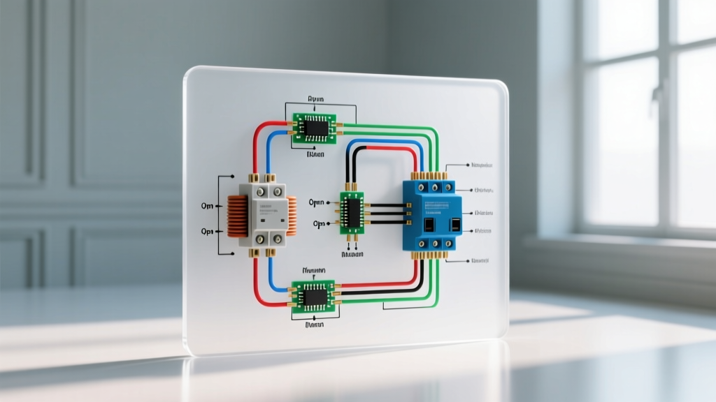
Imagine the circuit divided into two isolated loops: the Control Loop (120V) and the Power Loop (240V).
1. The 120V Control Loop (3-Way Switches)
- Panel to Switch 1: Run a 120V hot and neutral from a standard 15A/20A 120V breaker. The hot connects to the Common screw on Switch 1.
- Travelers: Run 12/3 cable between Switch 1 and Switch 2. Red and Black go to the brass traveler screws.
- Switch 2 to Contactor Coil (A1): The Common screw on Switch 2 connects to the A1 terminal on the contactor coil.
- Neutral Return: Run a 120V neutral wire directly from the panel to the A2 terminal on the contactor coil.
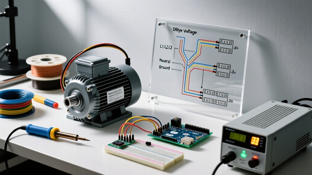
2. The 240V Power Loop (Motor Feed)
- Breaker to Contactor: The 240V hot legs (Black and Red from a double-pole breaker) land on the L1 and L2 main line terminals of the contactor.
- Contactor to Motor: The load side of the contactor (T1 and T2) runs directly to the motor's L1 and L2 terminal block.
- Grounding: The equipment grounding conductor (EGC) runs continuously from the main panel ground bar directly to the motor chassis, bypassing the contactor entirely.
How it works: When you flip either 3-way switch to complete the 120V control circuit, the contactor coil energizes. This creates a magnetic field that pulls the heavy-duty silver-alloy contacts closed, safely delivering 240V to the motor without any high-amperage arcing occurring inside your wall switches.
Common Failure Modes & Troubleshooting
Even with a perfect diagram, field conditions can introduce errors. Here are the most common issues encountered when wiring 3-way motor controls:
1. Phantom Voltage on Travelers
When testing with a high-impedance digital multimeter, you may read 40V to 90V on the 'dead' traveler wire. This is capacitive coupling—induced voltage from the live traveler running parallel in the same 12/3 Romex jacket. Fix: Use a low-impedance voltage tester (LoZ) or a solenoid voltage tester (Wiggy) to confirm true zero voltage before touching wires.
2. Miswired Common Terminals
The most frequent DIY error is connecting the line/load hot to a brass traveler screw, and a traveler wire to the black common screw. This results in a circuit that only works when the other switch is in one specific position. Fix: Always identify the common wire by tagging it with black electrical tape before removing the old switch, or use a continuity tester to find the screw that toggles continuity with the two brass screws.
3. Contactor Chatter (Humming)
If your contactor buzzes loudly or rapidly clicks on and off, the 120V control circuit is experiencing severe voltage drop, often due to undersized traveler wires or loose terminal connections. Fix: Ensure all 12/3 traveler connections are torqued to spec and that the 120V control breaker is not overloaded with other shop accessories.
Frequently Asked Questions (FAQ)
Can I use a smart 3-way switch for motor control?
Most smart 3-way switches (like the Lutron Caseta or Kasa Smart) contain internal solid-state relays or delicate electronic bypass circuits designed strictly for LED and incandescent lighting. Using them to switch an inductive motor load will likely fry the internal logic board. Stick to mechanical heavy-duty toggles or smart contactor setups for motors.
Does a 240V motor need a neutral wire?
Standard single-phase 240V motors (like dust collectors and air compressors) do not require a neutral. They require two hot legs and an equipment ground. However, if your motor control panel includes a 120V transformer for PLC logic or indicator lights, a neutral may be required at the control enclosure.
What is the 2026 NEC requirement for GFCI protection on hardwired motors?
While receptacles in garages and workshops strictly require GFCI protection, hardwired motors dedicated to specific appliances (like a central dust collection system) are generally exempt from GFCI requirements under NEC Article 210.8, provided they are not located in damp or wet areas. Always verify with your local Authority Having Jurisdiction (AHJ), as local 2026 amendments may vary.