
The Shift from Paper to Digital: Why Auto Wiring Software Matters in 2026
Modern vehicles are no longer simple 12-volt mechanical machines; they are rolling data centers. A typical 2026 luxury SUV contains over 3 miles of wiring and upwards of 100 distinct Electronic Control Units (ECUs) communicating via CAN-FD, LIN, and Automotive Ethernet networks. When diagnosing a parasitic draw or a multiplexed communication fault, relying on static PDF manuals is a recipe for misdiagnosis and wasted labor hours. This is where professional auto electrical wiring diagram software becomes the most critical tool in your diagnostic arsenal.
Whether you are an independent shop owner trying to trace a short-to-ground in a Body Control Module (BCM), or a custom fabricator designing a standalone harness for an LS or EV swap, the right software bridges the gap between a physical symptom and an electrical root cause. Below, we break down the industry-standard platforms, compare their 2026 pricing models, and provide a technical reference guide for reading digital schematics like an OEM engineer.
Top Tier Auto Electrical Wiring Diagram Software (2026 Comparison Matrix)
| Software Platform | Best Application | Est. 2026 Pricing | Interactive Tracing | OEM Coverage Depth |
|---|---|---|---|---|
| Mitchell 1 ProDemand | Professional Diagnostics & Repair | $425 - $475 / month | Yes (Wire Tracing Tool) | Exceptional (Full OEM) |
| ALLDATA Repair | Collision & General Mechanical | $225 - $275 / month | Limited (Mostly Static) | High (Some PDF limits) |
| EdrawMax Auto | Custom Harness & Restomod Design | $99 Lifetime / $5.99 Mo | N/A (Design Tool) | N/A (User Generated) |
| AutoCAD Electrical | OEM Harness Engineering | $1,975 / year | Yes (Schematic Logic) | N/A (Engineering Tool) |
Deep Dive: The Industry Standards for Diagnostics
Mitchell 1 ProDemand: The Diagnostic Gold Standard
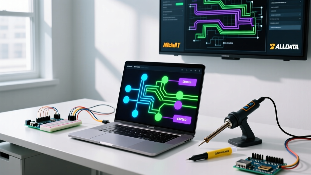
For professional technicians, Mitchell 1 ProDemand remains the undisputed heavyweight in auto electrical wiring diagram software. Its killer feature is the Interactive Wire Tracing tool. In older systems, if a circuit spanned three different pages (e.g., from the under-hood fuse box, through the firewall grommet, to the dash instrument cluster), you had to manually cross-reference page numbers and connector pinouts.
With ProDemand, clicking on a specific wire node highlights the entire circuit path across all schematic pages in red. It also integrates directly with component testing procedures, providing expected voltage drops and resistance values at specific breakout pins. For shops dealing with late-model European vehicles (BMW, Audi, Mercedes) where wiring faults often involve gateway module handshakes, this interactive layer saves hours of manual tracing.
ALLDATA Repair: The Independent Shop Workhorse
ALLDATA is a staple in the industry, heavily favored by collision repair centers and general mechanical shops. While its mechanical and torque-spec databases are flawless, its auto electrical wiring diagram software capabilities can sometimes lag behind Mitchell 1 in terms of interactivity. Many OEM diagrams in ALLDATA are delivered as high-resolution vector images or flattened PDFs. You can zoom in without pixelation—which is crucial for reading tiny 8-pin Deutsch connector pinouts—but you cannot click a wire to trace it across pages. However, at roughly half the monthly cost of ProDemand, it remains a highly viable option for shops that don't specialize exclusively in heavy electrical diagnostics.
Custom Harness Design: Software for Restomods and EV Swaps
What if you aren't repairing a factory vehicle, but building one from scratch? The rise of EV conversions and custom engine swaps has created a massive demand for schematic design tools.
- EdrawMax: An accessible, drag-and-drop diagramming tool with a robust library of automotive electrical symbols (relays, fuses, DIN-standard terminals, and CAN bus nodes). It is perfect for mapping out a custom Painless Performance or standalone Haltech harness before cutting and crimping a single wire.
- AutoCAD Electrical: Used by high-end motorsport teams and boutique EV conversion shops (like those building custom Porsche 911 EV swaps). It allows for precise wire routing, automated Bill of Materials (BOM) generation, and exact terminal crimp specifications. The steep learning curve and $1,975+ annual price tag reserve this for serious engineering firms.
Reference Guide: Reading Digital Auto Schematics
Having the software is only half the battle; understanding the OEM shorthand is the other. Most global manufacturers adhere to SAE International and DIN standards for schematic notation. Here is a quick-reference guide to the most common symbols you will encounter in your software.
DIN 72552 Terminal Designations
European and many Asian manufacturers use DIN 72552 to label ignition and power states. Memorize these to trace power flows instantly:
- Terminal 30: Direct Battery Positive (Hot at all times).
- Terminal 15: Ignition Switched Power (Hot in Run/Start).
- Terminal 31: Direct Ground (Chassis/Battery Negative).
- Terminal 50: Starter Motor Control (Hot only in Crank).
- Terminal X: Load Reduction Relay (Power cut during crank to save battery for starter).
Node and Splice Identifiers
When a wire splits to feed multiple modules, the software will denote a splice pack. In GM and Ford diagrams, look for S-prefix identifiers (e.g., S104, S210). These represent physical soldered or ultrasonic splice joints wrapped in heat shrink, usually located deep inside the main harness loom. Expert Tip: Never cut into a factory splice pack to add an aftermarket accessory; the resulting change in resistance can trigger CAN-bus ghost faults.
Ground Distribution Points
Grounds are denoted with a G-prefix (e.g., G101, G204). The software will usually provide a 'Ground Location View'—a 3D or 2D illustration showing exactly which sheet metal bolt the ground ring terminal is attached to. Over 60% of 'unexplainable' electrical gremlins are caused by corrosion at these specific G-nodes.
Step-by-Step: Diagnosing a Multiplexed Network Fault
Let us walk through a real-world diagnostic workflow using auto electrical wiring diagram software to solve a complex issue: A 2024 truck where the instrument cluster goes dark intermittently, but no hard DTCs (Diagnostic Trouble Codes) are stored.
- Pull the Network Topology: Open the software and navigate to the 'Communication Networks' section, not the 'Instrument Cluster' power section. Modern clusters are often just displays driven by a Gateway Module.
- Identify the Bus Type: The diagram shows the cluster is on the High-Speed CAN-C bus. According to ISO 15765-4 standards, this requires a twisted pair (CAN-H and CAN-L) terminating at 60 ohms.
- Trace the Gateway Routing: The software reveals that the cluster does not wire directly to the PCM. It routes through the Body Control Module (BCM). If the BCM loses its Terminal 30 (Battery) or Terminal 31 (Ground) connection, it drops the cluster off the network.
- Locate the Ground Node: Using the software's ground locator tool, you find G204 is located behind the driver's side kick panel. Physical inspection reveals a loose 10mm bolt causing a micro-disconnect when the door is slammed.
Pro-Troubleshooter Insight: Never use a standard Digital Multimeter (DMM) to diagnose CAN bus wiring based solely on a software diagram. A DMM will show an 'average' voltage of 2.5V on CAN-H and 2.5V on CAN-L, which looks normal. You must use an oscilloscope to verify the square-wave digital handshake. The wiring diagram software tells you where to probe; the scope tells you what the signal is actually doing.
Common Edge Cases & Software Limitations
Even the best auto electrical wiring diagram software has blind spots that technicians must be aware of:
- Mid-Year Production Splits: OEMs frequently change wiring harnesses mid-production year without changing the vehicle's VIN prefix. Always cross-reference the software's 'Production Date' filter with the physical build sticker on the driver's door jamb.
- Dealer-Only Flash Updates: A wiring diagram might show a direct hardwired connection between a sensor and an ECU. However, a Technical Service Bulletin (TSB)—often linked directly within Mitchell 1 or ALLDATA—might reveal that the 'fix' for a specific fault code is not a wiring repair, but a software reflash that changes how the ECU interprets the voltage signal.
- Aftermarket 'Piggyback' Modules: If a used vehicle has an aftermarket alarm or remote start installed, the physical wiring will deviate from the OEM software diagram. Always look for Scotch-Loks, T-taps, or messy electrical tape near the steering column and BCM as your first step before trusting the digital schematic.
Final Verdict: Choosing Your Digital Companion
If your daily workflow involves diagnosing late-model OEM electrical faults, tracing parasitic draws, and navigating complex gateway modules, a subscription to Mitchell 1 ProDemand is a non-negotiable business expense. The interactive wire tracing alone pays for the subscription by saving just one or two hours of misdiagnosis per month. For custom fabricators, restomod builders, and EV swap engineers, EdrawMax or AutoCAD Electrical provides the blank canvas needed to design safe, reliable, and documented custom harnesses. In the highly multiplexed automotive landscape of 2026, guessing is no longer an option; let the software guide your multimeter.