
Understanding the Kawasaki Bayou 220 (KLF220) Electrical Architecture
The Kawasaki Bayou 220 (model code KLF220), produced continuously from 1988 through 2002, remains one of the most reliable and mechanically straightforward utility ATVs ever built. Its 215cc air-cooled single-cylinder engine relies on a classic flywheel magneto electrical system. As of 2026, with original OEM parts becoming increasingly scarce, understanding the exact wiring diagram for Kawasaki Bayou 220 models is critical for owners performing restorations, diagnosing parasitic draws, or swapping to high-quality aftermarket components from manufacturers like Rick's Motorsport Electrics.
Unlike modern fuel-injected quads with complex ECU networks, the KLF220 harness is entirely analog. It separates the ignition circuit from the lighting and charging circuits, meaning a failure in your headlight wiring will not prevent the engine from sparking. This guide breaks down the factory harness routing, wire color codes, and multimeter testing procedures required to keep your Bayou 220 running flawlessly.
Core Components of the Bayou 220 Wiring Harness
Stator and Flywheel Magneto Assembly
The KLF220 uses a dual-coil stator mounted behind the left-side engine cover. The lighting coil generates raw AC voltage strictly for the headlight and taillight. The charging coil feeds the regulator/rectifier to maintain the 12V battery (typically a 12N12A-4A-1 for early models or a YTX14AHL-BS for later electric-start variants). The pulse pickup coil sits just outside the flywheel and reads the timing tab to tell the CDI when to fire.
CDI Unit and Ignition Circuit
The Capacitor Discharge Ignition (CDI) box (OEM part #21119-1173) is the brain of the spark system. It receives a low-voltage pulse from the pickup coil (which should read 90–150 ohms of resistance) and discharges high voltage into the ignition coil (OEM #21121-1121). The handlebar kill switch functions by grounding the CDI's black/yellow wire, instantly collapsing the ignition field and killing the engine.
Regulator/Rectifier and Battery Circuit
The regulator/rectifier (OEM #21062-1121) takes the wild, fluctuating AC voltage from the stator's charging coil, rectifies it into DC voltage, and regulates it down to a safe 13.5V–14.5V to charge the battery without boiling the electrolyte.
Kawasaki Bayou 220 Wire Color Code Reference Table
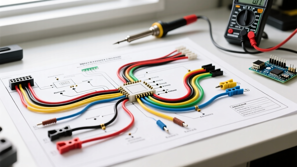
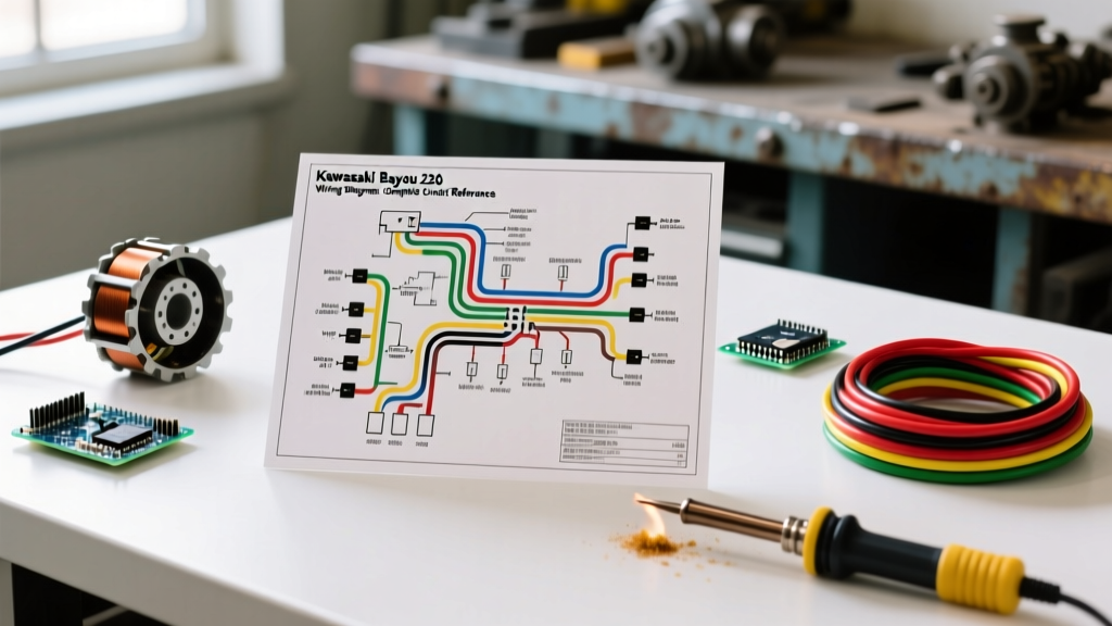
When tracing the wiring diagram for Kawasaki Bayou 220 harnesses, adhering to the factory color codes is essential. Note that UV exposure and engine heat can fade 20-year-old wire insulation, making black and dark green wires look identical. Always verify continuity with a multimeter rather than relying solely on visual color matching.
| Wire Color | Function | Circuit Path / Destination |
|---|---|---|
| Red | Battery Positive (12V DC) | Main Fuse to Ignition Switch |
| Black | System Ground | Frame / Battery Negative Terminal |
| White | Lighting Coil Output (AC) | Stator to Headlight/Taillight Switch |
| Yellow | Charging Coil Output (AC) | Stator to Regulator/Rectifier |
| Black/Yellow | Ignition Kill Switch | CDI to Handlebar Engine Stop Switch |
| White/Red | Pickup Coil Signal | Stator Pulse Trigger to CDI |
| Grey | Ignition 'ON' Power | Ignition Switch to CDI / Accessories |
| Yellow/Red | Starter Solenoid Trigger | Start Button to Solenoid Relay |
Step-by-Step Troubleshooting for Common KLF220 Electrical Faults
Scenario 1: Engine Cranks but Has No Spark
- Isolate the CDI: Disconnect the main multi-pin harness plug from the CDI unit to rule out a shorted kill switch or wiring harness.
- Test the Pickup Coil: Set your digital multimeter to the 200Ω (Ohms) setting. Probe the white/red and black/white wires on the stator side of the disconnected plug.
- Read the Resistance: A healthy KLF220 pickup coil will read between 90 and 150 ohms. If the reading is infinite (OL), the internal copper windings are broken, and the stator must be replaced.
- Check the Kill Circuit: If the pickup coil tests fine, check the black/yellow kill wire for a short to ground. A frayed kill wire touching the frame near the steering stem will permanently ground the CDI, preventing the spark plug from firing.
Scenario 2: Battery Keeps Dying (No Charge)
- Test Stator AC Output: Start the ATV and let it idle. Set your multimeter to AC Voltage (V~). Probe the yellow wire coming from the stator before it enters the regulator/rectifier. You should see at least 15V AC at idle, climbing to 30V+ AC at 3000 RPM.
- Test Rectifier DC Output: Set the meter to DC Voltage (V-). Probe the battery terminals with the engine running at 3000 RPM.
- Diagnose the Failure: A functioning regulator/rectifier will output between 13.5V and 14.5V DC. If your AC input from the stator is high, but the DC output at the battery is below 13V, the internal diodes in the rectifier have failed and the unit must be replaced.
Critical Upgrade Warning: AC vs. DC Lighting
The most common and expensive mistake DIYers make when modifying older ATVs is wiring modern 12V DC LED light bars directly to the factory headlight switch.
The factory lighting coil on the Bayou 220 outputs raw, unrectified Alternating Current (AC). Standard 12V LED light bars and auxiliary work lights require Direct Current (DC). Wiring DC LEDs to the AC lighting coil will cause severe flickering, drastically reduce the lifespan of the LEDs, and eventually destroy the internal driver board due to reverse-voltage spikes.
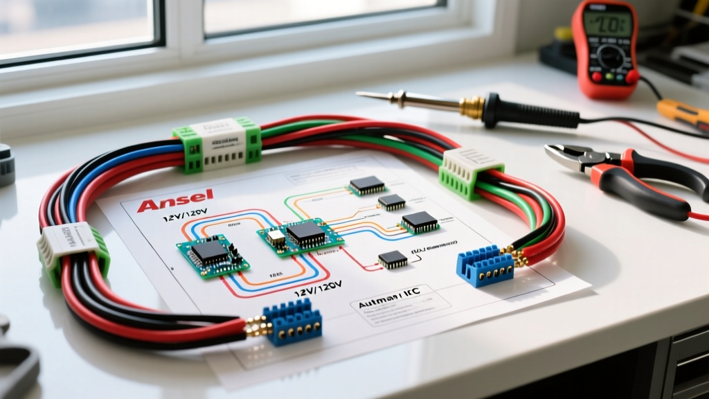
To run auxiliary DC accessories, you must wire a dedicated 40A automotive relay directly to the battery's positive terminal. Use the ignition switch's 12V DC output (Grey wire) as the low-amperage trigger signal for the relay coil. Always protect this new high-draw circuit with an inline ANL fuse rated 20% higher than your accessory's maximum amperage draw. For detailed OEM exploded diagrams and specific relay part numbers, enthusiasts frequently cross-reference the Kawasaki Parts House ATV portal or consult archived factory service manuals via Carls Alter's Motorcycle and ATV Manual Repository.
Winch Wiring and High-Draw Accessory Integration
Installing a 2,000-lb or 3,000-lb winch on a KLF220 pushes the absolute limits of its stock 12Ah battery. Winches can pull 120+ amps under heavy load or when spooling in dead weight. Never wire a winch solenoid through the ATV's factory wiring harness.
Use a minimum 4-gauge stranded copper wire routed directly from the battery terminals to the winch contactor. Install a heavy-duty marine-grade circuit breaker (150A) on the positive lead within 6 inches of the battery terminal. This prevents catastrophic harness fires in the event of a solenoid weld-out or a dead short in the winch motor. Furthermore, consider upgrading the factory battery to a high-CCA AGM (Absorbent Glass Mat) battery to handle the extreme voltage sag that occurs during heavy winching operations.
Frequently Asked Questions (FAQ)
Can I use a generic universal 5-pin CDI on my Bayou 220?
No. The KLF220 uses a specific magneto-triggered AC-CDI. Many generic 'universal' CDIs sold online are DC-CDIs designed for modern scooters and will not fire without extensive stator modifications and a 12V DC power feed. Always use an OEM replacement or a model-specific aftermarket unit.
Why do my OEM headlights blow out at high RPM?
Because the lighting coil outputs AC, voltage spikes occur as engine RPM increases. The factory halogen bulb acts as its own resistor to handle minor fluctuations, but severe spikes will blow the filament. If this happens frequently, your flywheel magnets may be degrading, or you need to install an inline AC voltage regulator specifically designed for motorcycle lighting coils.
Where is the main fuse located?
The main 15A or 20A glass tube fuse is located inside the cylindrical fuse holder on the red positive battery cable, usually tucked just behind the front grill or under the front fender well near the battery box. Always carry a spare fuse and a multimeter when riding remote trails.