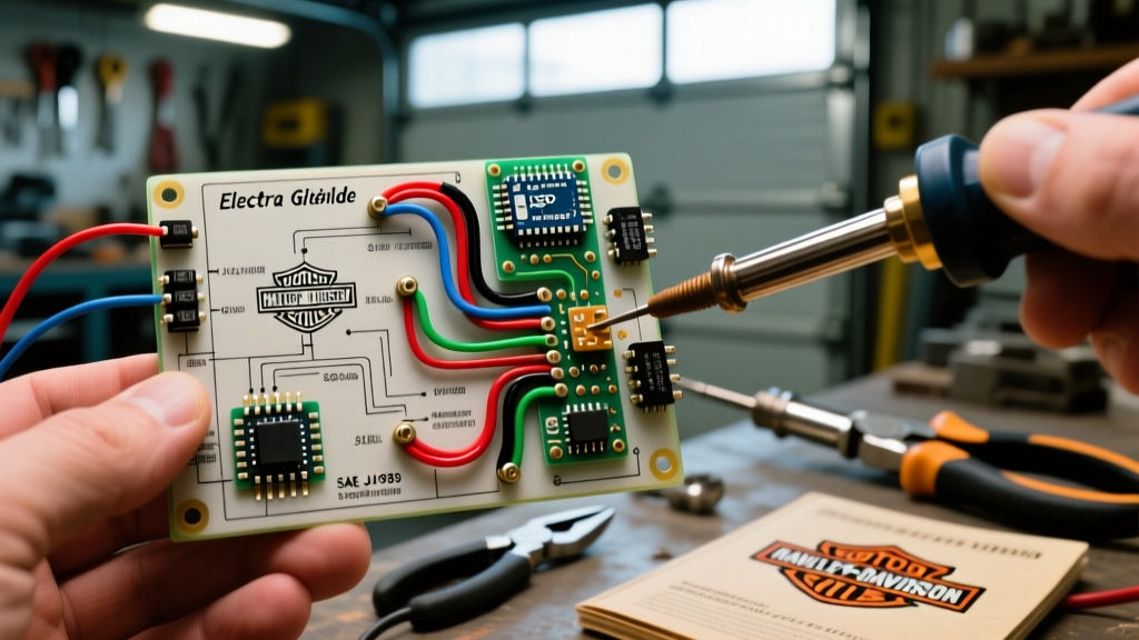

The Hidden Dangers of Oversimplified Motorcycle Wiring
Harley-Davidson Electra Glide touring motorcycles are a staple of the open road, renowned for their comfort and heavy customization potential. From auxiliary highway lights and heated grips to Tour-Pak audio upgrades, owners are constantly modifying their rigs. Consequently, thousands of riders search for electra glide harley wiring diagrams simple enough to follow on a Saturday afternoon in the garage. However, in the realm of automotive and motorcycle electrical systems, 'simple' often translates to 'unsafe' when critical safety steps, proper load calculations, and SAE (Society of Automotive Engineers) compliance standards are ignored.
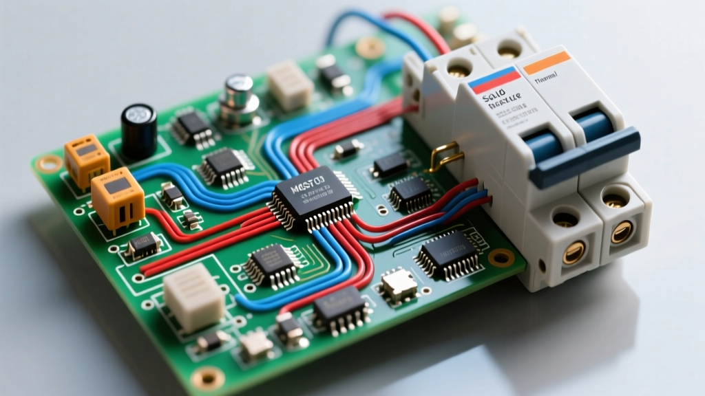
A stripped-down diagram might show you how to connect a switch directly to a light bar, but it frequently omits inline fusing, relay integration, and proper environmental sealing. This negligence leads to melted harnesses, parasitic battery drains, and catastrophic electrical fires. As we navigate the 2026 touring season, understanding the safety and code compliance behind these diagrams is not just recommended—it is mandatory for anyone modifying their motorcycle.
Core Safety Standards: SAE J1128 and J1455
When sourcing wire and connectors for your Electra Glide, you must adhere to established automotive standards. The SAE J1128 Low Tension Primary Cable Standard dictates the requirements for wire insulation used in vehicle electrical systems. For under-tank and engine-proximate routing, you must use cross-linked polyethylene (XLPE) insulated wire, such as TXL, GXL, or SXL. Standard PVC wire (like THHN used in household wiring) will melt and short out when exposed to the radiant heat of a Milwaukee-Eight or Revolution Max engine.
Furthermore, NHTSA Vehicle Safety and Modification Guidelines emphasize the importance of maintaining the integrity of original equipment manufacturer (OEM) safety circuits. This means never bypassing factory fuses or tapping into critical CAN bus networks without proper isolation.
Wire Gauge Selection & Ampacity Matrix
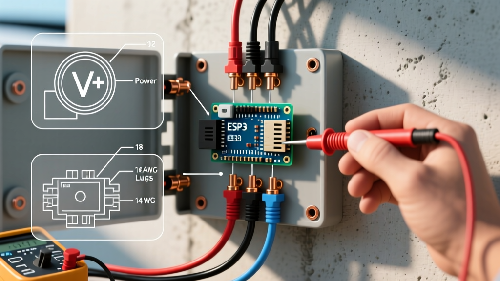
Using the correct American Wire Gauge (AWG) is the first line of defense against electrical fires. The following matrix outlines the maximum continuous amperage for chassis wiring (single wire in free air) and specific Electra Glide applications.
| AWG Size | Max Amps (Chassis) | Common Electra Glide Application | Recommended Fuse Size |
|---|---|---|---|
| 18 AWG | 6A | LED Accent Lights, CAN Bus Signals, USB Ports | 5A MINI |
| 16 AWG | 10A | Horn Upgrades, License Plate Lights, GPS Power | 7.5A ATC |
| 14 AWG | 15A | Standard Auxiliary Highway Lights, Fog Lamps | 10A ATC |
| 12 AWG | 20A | Heated Grips, Heated Seats, Tour-Pak Amplifiers | 15A ATC |
| 10 AWG | 30A | Main Accessory Power Bus, Winches (Trike models) | 25A ATC |
The CAN Bus Trap: 2014–2026 Project Rushmore & Beyond
One of the most common failure modes when following outdated or overly simple wiring diagrams on modern Electra Glides is CAN bus interference. Starting with the 2014 Project Rushmore models and continuing through the 2026 touring lineup, Harley-Davidson utilizes a Controller Area Network (CAN bus) to manage lighting, gauges, and the Body Control Module (BCM).
Expert Warning: Never use a 'scotch lock' or vampire tap to splice into the tail light or brake light wire for a brake light modulator or trailer harness on a 2014+ Electra Glide. The BCM monitors circuit resistance; an improper splice will trigger a Diagnostic Trouble Code (DTC), illuminate the ABS/Check Engine light, or cause the BCM to shut down the lighting circuit entirely to prevent a perceived short.
Instead, utilize the dedicated accessory power connector located under the seat or left side cover, or use a CAN-safe digital interface module that reads the CAN-H and CAN-L signals without drawing load from the data lines.
Step-by-Step: Safe Relay Integration for Aux Lights
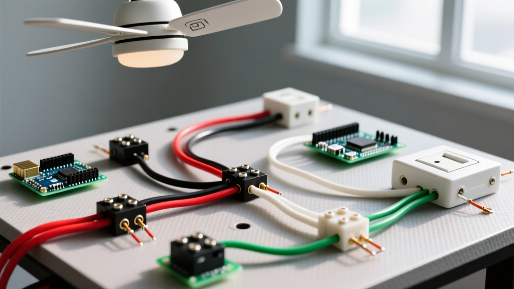
Many simple diagrams show a switch wired directly to high-draw auxiliary lights. This is a severe fire hazard, as the handlebar switch and thin gauge wiring will overheat under a 15A+ load. You must use a Bosch-style ISO mini relay (e.g., Hella 4RA 003 510-081). Here is the compliant, safe wiring sequence:
- Pin 30 (Power In): Run 12 AWG wire directly from the positive battery terminal. Install an inline ATC fuse holder within 6 inches of the battery. Size the fuse to the accessory load (e.g., 10A for two 55W halogen lights).
- Pin 87 (Power Out): Run 14 AWG wire from Pin 87 to the positive terminal of your auxiliary lights.
- Pin 86 (Trigger In): Connect a low-draw trigger wire (18 AWG) to a switched ignition source or your handlebar toggle switch. This circuit only needs to handle the relay coil draw (approx. 0.15A).
- Pin 85 (Ground): Ground this pin to a clean, unpainted metal point on the frame, or run it back to the battery negative. Use a star washer to bite through the clear coat or powder coat.
Environmental Sealing and the 'Fairing Ground' Fallacy
Motorcycle wiring is subjected to high-pressure car washes, torrential rain, and extreme vibration. The SAE J1455 standard outlines environmental testing for heavy-duty vehicle components, and your wiring should reflect this resilience.
- Adhesive-Lined Heat Shrink: Never use standard vinyl electrical tape to seal splices; the adhesive degrades in high heat. Use 3M FP-301 or equivalent dual-wall, adhesive-lined heat shrink. When heated, the inner meltable layer seals out moisture completely.
- Waterproof Connectors: For components you may need to remove (like fairing speakers or auxiliary light pods), use Deutsch DT series or TE Connectivity Superseal 1.5 connectors. These feature silicone grommets and secondary locks to prevent vibration-induced pin back-out.
- The Fairing Ground Trap: A notorious error in Electra Glide modifications is grounding accessories to the handlebars, triple tree, or fairing brackets. These components are often isolated by rubber mounts or suffer from corrosion at the pivot points, leading to severe voltage drop and flickering lights. Always run a dedicated ground wire back to the battery negative or the main OEM ground bus block on the frame.
Voltage Drop on Long Runs: The Tour-Pak Challenge
The Electra Glide's extended wheelbase and large Tour-Pak create exceptionally long wire runs. If you are powering a 10A heated seat or an amplifier in the rear trunk using 16 AWG wire over a 12-foot run, you will experience significant voltage drop. By the time the current reaches the accessory, it may be operating at 11V instead of 13.8V, leading to overheating and premature component failure. Always upsizing your wire by one gauge (e.g., dropping from 14 AWG to 12 AWG) for any run exceeding 8 feet is a critical compliance step that simple diagrams routinely ignore.
Conclusion: Safety Over Simplicity
While the appeal of electra glide harley wiring diagrams simple in design is understandable, your motorcycle's electrical system demands respect and precision. By adhering to SAE wire standards, calculating proper gauge and fuse sizes, isolating sensitive CAN bus networks, and utilizing environmental sealing, you ensure that your touring rig remains safe, reliable, and road-legal for every mile ahead. Invest in a quality digital multimeter, a proper terminal crimping tool (never use pliers), and take the time to wire it right the first time.