
Introduction to Halo Headlight Electrical Integration
Halo headlights, commonly known as Angel Eyes, have evolved significantly since their inception. As of 2026, the aftermarket and OEM landscape is dominated by high-efficiency COB (Chip-on-Board) LED rings and RGBW addressable halos, though legacy CCFL (Cold Cathode Fluorescent Lamp) tubes remain relevant for classic car restorations. Regardless of the light source, integrating these rings into a vehicle's existing lighting harness requires strict adherence to wire gauge sizing and automotive color codes. Tapping directly into factory headlight wires without proper relay isolation often leads to voltage drop, melted harnesses, and CANbus communication errors.
This comprehensive reference guide provides the exact wiring diagram for halo headlights, focusing on wire gauge selection, standard color coding, and relay integration to ensure a safe, flicker-free installation that complies with modern automotive electrical standards.
Wire Gauge & Ampacity Selection Matrix
Selecting the correct American Wire Gauge (AWG) is critical. Undersized wires create resistance, leading to heat buildup and dim halos. Oversized wires are unnecessarily stiff and difficult to route through tight headlight housings. According to the SAE J1128 standard for Low Tension Automotive Cable, wire ampacity must be matched to the specific circuit's maximum current draw, accounting for the high-temperature environment inside an engine bay.
| Circuit Application | Max Current Draw | Recommended AWG | Inline Fuse Size |
|---|---|---|---|
| Halo Rings (LED COB/SMD) | 0.5A - 1.5A | 18 AWG | 5A Mini Blade |
| Halo Rings (CCFL w/ Inverter) | 2.0A - 3.0A | 16 AWG | 5A Mini Blade |
| Relay Control Coil (Pins 85/86) | 0.2A - 0.5A | 18 AWG | N/A (Tapped Circuit) |
| Main Power Feed (Pin 30) | 15A - 20A | 12 AWG | 20A ATC/ATO |
| Halo Power Output (Pin 87) | 10A - 15A | 14 AWG | 10A ATC/ATO |
Expert Tip: Always use SAE-rated GXL or TXL cross-linked polyethylene insulated wire for engine bay routing. Standard PVC-insulated wire (THHN) will become brittle and crack when exposed to sustained under-hood temperatures exceeding 105°C.
Automotive Color Code Reference for Halo Kits
While aftermarket halo kit manufacturers occasionally deviate from standards, adhering to standard automotive wiring color codes ensures that future diagnostics and modifications can be performed safely. When building a custom harness for your halo headlights, use the following color conventions:
- Red: Constant 12V Battery Power or Switched 12V Primary Feed.
- Black: Chassis Ground (Must be sanded to bare metal for optimal conductivity).
- White: Switched Accessory / DRL (Daytime Running Light) Trigger.
- Amber/Yellow: Turn Signal Trigger (Tapped from factory turn signal positive).
- Blue: High Beam Trigger (Often used to dim halos or switch halo colors during high beam flash).
- Green: RGB/RGBW Data Signal (For Bluetooth or RF-controlled color-changing halos).
The Core Wiring Diagram for Halo Headlights
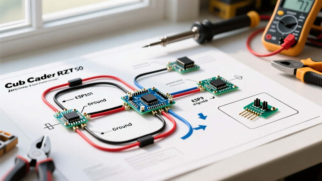
The most reliable method for wiring halo headlights is utilizing a standard Bosch-style 4-pin automotive relay. This isolates the high-current draw of the main headlights (if powering halos through the headlight circuit) or provides a robust switched power source directly from the battery, triggered by a low-current DRL or accessory wire. For a detailed visual breakdown of relay internals, refer to the MGI SpeedWare automotive relay wiring guide.
Step-by-Step Relay Integration Flow
- Pin 30 (Power In): Run a 12 AWG Red wire from the vehicle's positive battery terminal. Install a 20A inline ATC fuse within 8 inches of the battery post to protect the entire harness in the event of a short circuit.
- Pin 87 (Power Out): Connect a 14 AWG Red wire from Pin 87 to the positive input of your Halo LED drivers or CCFL inverters. Install a 10A inline fuse on this branch if the drivers do not have internal overcurrent protection.
- Pin 86 (Trigger In): Run an 18 AWG White wire to your desired trigger source. For DRL functionality, tap into the factory DRL wire or a switched ignition fuse in the cabin fuse box using an Add-A-Circuit (piggyback) fuse tap.
- Pin 85 (Ground): Connect an 18 AWG Black wire to a clean, unpainted chassis ground point. Use a ring terminal and secure it with a star washer to bite through the metal for a zero-resistance ground.
- Grounding the Halos: Connect the negative (Black) wires from both the left and right halo drivers directly to the chassis ground, or route them back to the relay vicinity to create a centralized ground bus.
Advanced Integration: DRL, Turn Signals, and PWM Decoders
Modern vehicles (2018-2026 models) rarely use simple 12V switched signals for Daytime Running Lights. Instead, they utilize PWM (Pulse Width Modulation) to dim the DRLs or multiplexed CANbus/LIN bus networks to communicate with lighting modules. If you tap a PWM DRL wire directly into Pin 86 of your relay, the relay will rapidly click, and your halos will flicker violently.
Solving PWM Flicker
To resolve this, you must install a PWM-to-DC Signal Decoder (often sold as an anti-flicker module or capacitor bank) between the factory DRL trigger wire and Pin 86 of the relay. This module smooths the pulsed signal into a steady 12V DC output, allowing the relay to engage cleanly.
Turn Signal Integration & Hyperflashing
If your halo kit features an integrated amber turn signal sequence (e.g., sequential sweeping halos), tapping into the factory turn signal wire can cause hyperflashing. This occurs because the vehicle's Body Control Module (BCM) detects a lower-than-expected current draw (since LED halos draw less current than incandescent bulbs) and assumes a bulb is out.
- Solution 1 (Load Resistors): Wire a 50W 6-ohm load resistor in parallel with the turn signal trigger wire. Warning: These resistors generate extreme heat and must be mounted to a metal chassis surface, away from plastic or wiring.
- Solution 2 (CANbus Decoders): Use an active CANbus decoder module that emulates the exact impedance of a factory 21W incandescent bulb without generating excess heat.
CCFL vs. LED Halo Hardware Comparison
Understanding the hardware differences is vital when interpreting the wiring diagram for halo headlights, as the high-voltage requirements of CCFL dictate entirely different routing rules compared to low-voltage LED systems.
| Feature | CCFL Halo Rings (Legacy/Restoration) | COB/SMD LED Halo Rings (Modern Standard) |
|---|---|---|
| Operating Voltage | 12V DC Input / 1000V+ AC Ignition Output | 9V - 16V DC Constant Current |
| Required Hardware | High-Voltage Inverters (1 per pair of rings) | Constant Current LED Drivers / CANbus Decoders |
| Wiring Hazard | High-voltage output wires can arc to chassis if insulation is nicked. | Low voltage, but susceptible to voltage spikes and CANbus polling. |
| Routing Rule | Keep inverter output wires at least 2 inches away from ECU and metal. | Standard routing; keep away from exhaust headers and moving belts. |
Critical Failure Modes & Troubleshooting
Even with a perfect wiring diagram for halo headlights, real-world installations encounter edge cases. Use this troubleshooting matrix to diagnose common issues:
1. Halos Illuminate When Car is Off (Parasitic Draw)
Cause: Pin 86 (Trigger) is wired to a constant 12V source instead of a switched ignition or DRL source, or the relay is installed backward (swapping Pins 30 and 87 can cause internal diode bypass issues in some relays).
Fix: Use a multimeter to verify the trigger wire drops to 0V when the ignition is turned off and the key is removed. Move the Add-A-Circuit tap to a true switched fuse (e.g., radio or wiper motor).
2. One Halo Ring is Dim or Flickering
Cause: Voltage drop on the ground side. Many installers daisy-chain the ground wires from the left and right halos, creating a bottleneck.
Fix: Run dedicated 18 AWG ground wires from each individual halo driver directly to the chassis ground. Ensure the grounding point is sanded to bare metal and treated with dielectric grease to prevent corrosion.
3. BCM Throws a 'Bulb Out' Warning on Dashboard
Cause: The vehicle's FMVSS lighting compliance monitoring system detects the low resistance of the LED halo drivers when tapped into the main headlight circuit.
Fix: Install a 9005/9006 CANbus error canceller between the factory headlight harness and the aftermarket headlight bulb, ensuring the BCM reads the correct load profile.
Final Best Practices for 2026 Installations
When executing the wiring diagram for halo headlights, abandon the use of generic 'vampire taps' or twist-and-tape connections. The modern standard for automotive wiring dictates the use of heat-shrink butt connectors with adhesive-lined interiors or solder-seal wire connectors. These provide a waterproof, vibration-proof seal that prevents copper oxidation inside the headlight housing. Always route wiring through the factory rubber headlight dust boots, using a slit and a dab of RTV silicone sealant to maintain the housing's IP67 weather resistance rating. Proper gauge selection, strict color coding, and relay isolation will ensure your halo headlights operate flawlessly for the life of the vehicle.