
Decoding the Wiring Diagram for a Kohler Engine
Whether you are retrofitting a commercial zero-turn mower, wiring a standalone water pump, or troubleshooting a residential generator, understanding the exact wiring diagram for a Kohler engine is critical. Kohler’s small engine lineup—particularly the heavy-duty Command PRO V-twins (CH/CV series) and the single-cylinder Courage (SV series)—relies on a robust but unforgiving electrical architecture. A single misrouted wire or undersized gauge can instantly destroy a $140 voltage regulator or fry the $600+ Electronic Control Unit (ECU) on Electronic Fuel Injection (EFI) models.
As of 2026, Kohler has transitioned many of its commercial Command PRO lines to closed-loop EFI and SMART-THROTTLE systems, which add CAN-bus communication layers to the traditional stator-and-regulator setup. This tutorial breaks down the foundational motor wiring principles for both legacy carbureted models and modern EFI platforms, providing actionable schematics, multimeter diagnostics, and wire gauge matrices.
The Anatomy of Kohler Charging and Ignition Systems
Before splicing a single connector, you must understand the three distinct electrical sub-systems present in almost every Kohler engine wiring harness:
- The Stator (Alternator): Mounted beneath the flywheel, the stator generates raw Alternating Current (AC) as the flywheel’s permanent magnets spin past its copper coils. Output ranges from 10 amps on basic Courage models to 33 amps on high-output Command PROs.
- The Voltage Regulator/Rectifier: This solid-state component converts the raw AC from the stator into smooth Direct Current (DC) to charge the battery and run 12V accessories (lights, PTO clutches, fuel pumps).
- The Ignition and Kill Circuit: Kohler utilizes a “ground-to-kill” logic. The ignition module (MDI or DSAI) fires continuously by default. To stop the engine, the key switch grounds the primary ignition wire, collapsing the magnetic field and killing the spark.
Step-by-Step Wiring Tutorial: Command PRO V-Twin (CH740/CV740)
The Command PRO 25-27 HP V-twin is the workhorse of the commercial landscaping industry. Here is how to properly wire the charging circuit based on the factory Kohler Engines Support schematics.
1. Stator to Regulator Routing
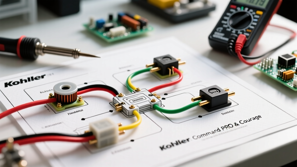
The stator outputs two (or sometimes three) AC wires, typically colored yellow or black. These must connect to the two AC terminals on the voltage regulator. Polarity does not matter on the AC side. Crucial Detail: Do not use standard push-on spade connectors here. The vibration of a V-twin will back them out over time. Use insulated male/female bullet connectors or the factory Molex plug, and secure them with dielectric grease.
2. The B+ (Battery Positive) Connection
This is where 90% of DIY wiring mistakes occur. The regulator has a third terminal, usually a threaded stud with a nut, labeled B+. This wire must route directly to the positive terminal of the battery or the main starter solenoid battery post.
WARNING: Never run the engine with the B+ wire disconnected. The regulator relies on the battery as a voltage sink. Without it, AC voltage will spike past 60V, instantly blowing the internal diodes and potentially damaging the PTO clutch diode.
3. Inline Fusing
Install a 30A ATC blade fuse holder on the B+ wire, positioned within 6 inches of the battery positive terminal. This protects the main harness from melting in the event of a dead short inside the regulator.
Kohler Stator and Regulator Compatibility Matrix
Mismatching a stator to a regulator is a common failure point. A 30A regulator connected to a 15A stator will overwork the stator, causing the epoxy encapsulation to melt. Use this matrix to verify your components:
| Engine Family | Stator Output | Stator Part # | Regulator Part # | Min. Wire Gauge (B+) |
|---|---|---|---|---|
| Courage (SV600-SV620) | 15 Amps | 20 030 02-S | 20 755 03-S | 12 AWG |
| Command PRO (CH/CV 20-23) | 20 Amps | 239 01-S | 25 755 03-S | 10 AWG |
| Command PRO (CH/CV 25-27) | 30 Amps | 239 02-S | 64 755 01-S | 10 AWG |
| Command PRO EFI (ECH749) | 33 Amps | 24 030 05-S | 64 755 04-S (SAM) | 8 AWG |
Critical Failure Modes and Multimeter Diagnostics
When troubleshooting a wiring diagram for a Kohler engine, skip the guesswork and use a digital multimeter (DMM). Here are the exact parameters for a healthy system at 3600 RPM (full operating throttle):
Diagnostic 1: Testing Stator AC Output
- Setup: Disconnect the stator plug from the regulator. Set DMM to VAC (AC Volts).
- Procedure: Probe the two stator pins. Run the engine at 3600 RPM.
- Expected Value: 28 to 35 VAC. If you read below 20 VAC, the stator is shorted internally, or the flywheel magnets have weakened (common if the flywheel was removed using a hammer instead of a proper puller, cracking the magnet ring).
Diagnostic 2: Testing Regulator DC Output
- Setup: Reconnect the regulator. Set DMM to VDC. Probe the battery terminals.
- Expected Value: 13.8V to 14.4V DC at 3600 RPM.
- Failure Mode: If voltage reads 15.5V+, the regulator’s internal shunt circuit has failed (overcharging). If it reads 12.2V and drops as RPM increases, the rectifier diodes are blown (no charging).
Wire Gauge Selection for Kohler Harnesses
Small engine environments feature high ambient heat (often exceeding 180°F near the cylinder heads) and severe vibration. According to standard AWG wire sizing data and NFPA National Electrical Code (NEC) guidelines for low-voltage DC applications, you must oversize your wire slightly to account for voltage drop and heat derating.
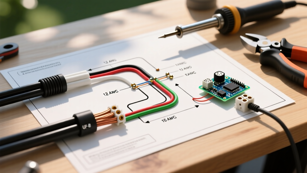
- Stator to Regulator (AC): 12 AWG stranded copper (minimum 105°C insulation rating, e.g., GXL or TXL automotive wire).
- Regulator B+ to Battery (DC): 10 AWG stranded copper for 20A/30A systems; 8 AWG for 33A EFI systems.
- Ignition Kill Wire: 16 AWG is sufficient, as it carries virtually zero amperage (only a signal ground).
- PTO Clutch Feed: 12 AWG. Electric PTO clutches draw 2 to 4 amps on engagement but can spike higher; voltage drop here causes premature clutch burnout.
EFI vs. Carburetor Wiring Differences (ECH Series)
If your wiring diagram for a Kohler engine involves an Electronic Fuel Injection (EFI) model like the ECH740 or ECH749, the complexity increases significantly. Unlike carbureted models that only need a kill wire and a charging circuit, EFI engines require a dedicated Main Power Relay.
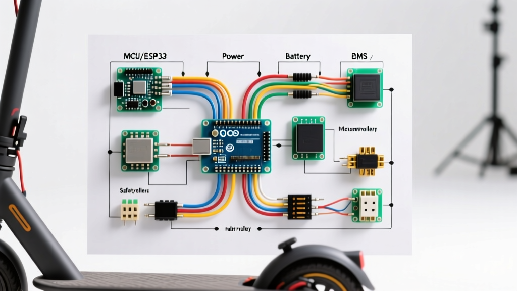
The ECU requires a clean, switched 12V source to power the fuel pump, injectors, and oxygen sensors. In 2026, Kohler’s latest SMART-THROTTLE systems also utilize a 4-pin Smart Alternator Module (SAM). The SAM not only regulates voltage but communicates engine RPM and load data back to the ECU to optimize the throttle stepper motor. Never bypass the SAM on an EFI engine to install a standard 3-pin regulator; the ECU will throw a CAN-bus fault code and default to limp mode (restricted to 2200 RPM).
Frequently Asked Questions
Can I use an automotive voltage regulator on a Kohler engine?
No. Automotive regulators (like those on older Chrysler or Ford alternators) are designed to control the excitation field of a rotating alternator. Kohler uses a permanent magnet stator, which requires a specific shunt-style regulator/rectifier to bleed off excess AC voltage as heat. Using an automotive part will result in immediate failure.
Why does my new Kohler voltage regulator get too hot to touch?
Shunt-style regulators dissipate excess stator energy as heat. It is normal for the regulator body to reach 140°F–160°F during operation. However, if the heat sink fins are melting the plastic connector housing, check your B+ wire gauge. A voltage drop on the B+ wire forces the regulator to work harder to maintain 14V at the battery, generating excessive localized heat.
How do I wire the ignition kill circuit to a safety interlock module?
Kohler’s DSAI (Digital Spark Advance Ignition) modules use a single kill wire. To integrate with a seat switch or PTO safety relay, wire the relay’s normally-open (NO) contact between the ignition kill wire and the engine chassis ground. When the safety condition is violated (e.g., operator leaves the seat with the PTO engaged), the relay closes, grounding the module and killing the spark instantly.