
The Role of the ATS in Class A Motorhomes and Expedition Rigs
When outfitting a Class A motorhome, luxury fifth-wheel, or custom expedition vehicle with a high-capacity onboard generator, managing the transition between shore power and generator power is critical. The wiring diagram for Generac transfer switch units in mobile applications differs significantly from residential standby setups. In the RV and expedition vehicle sector, the Generac 50-Amp Automatic Transfer Switch (commonly the Model 9854 or OEM-specific variants like the 6335 series) is the industry standard for rigs running dual 15,000 BTU roof air conditioners, residential refrigerators, and high-wattage inverter-charger systems.
Unlike home generators that rely on a 240V split-phase utility grid, RV environments deal with mobile vibration, extreme temperature fluctuations, and unique neutral-ground bonding requirements governed by the NFPA 1192 Standard on Recreational Vehicles. This guide provides a deep-dive technical breakdown of wiring, terminating, and troubleshooting a 50A Generac ATS specifically for vehicle chassis and coach integration.
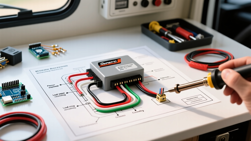
Decoding the Wiring Diagram for Generac Transfer Switch (50A RV Models)
The Generac 50A RV ATS is a double-pole, double-throw (DPDT) relay system designed to prioritize shore power. If shore power is lost, the internal logic board signals the generator to start, waits for a 30-second stabilization delay, and then engages the generator contactors. Understanding the wiring schematic requires breaking the system down into three distinct zones.
Shore Power Input (Source 1 - Preferred)
Shore power enters the ATS from the RV's exterior 50-amp marine-grade inlet (typically a Hubbell or Marinco twist-lock). The wiring diagram routes the incoming 120/240V split-phase power (L1, L2, Neutral, Ground) to the "SOURCE 1" or "SHORE" terminal block. Because shore power is the preferred source, the internal relays remain in the normally closed (NC) position for this circuit when de-energized, ensuring passive connection to the grid without drawing 12V DC standby current.
Generator Input (Source 2 - Backup)
The onboard generator (e.g., Generac QP series, Cummins Onan) feeds into the "SOURCE 2" or "GEN" terminal block. Crucially, the Generac RV ATS requires a 12V DC control signal to manage the switching logic. This 12V trigger is usually tapped from the generator's pre-heat or run circuit. When the generator's 120/240V output reaches nominal voltage and the 30-second time-delay elapses, the internal solenoid energizes, physically moving the contactors from Shore to Generator.
Load Output (Main RV Panel)
The "LOAD" terminals feed the RV's main AC distribution panel. In 50A RV applications, the Generac ATS switches both Line 1, Line 2, and the Neutral. Switching the neutral is a critical safety requirement in mobile applications to prevent backfeeding and ensure that the neutral-ground bond remains strictly at the active power source (the shore pedestal or the generator's internal stator), complying with Recreation Vehicle Industry Association (RVIA) electrical codes.
Terminal Pinout and Torque Specifications
Proper torque is non-negotiable in mobile environments. Vibration from the vehicle chassis and road harmonics can easily back out under-torqued terminal screws, leading to arcing, melted terminal blocks, and catastrophic coach fires. Use a calibrated inch-pound torque screwdriver for all terminations.
| Terminal ID | Function | Recommended Wire Gauge | Torque Specification |
|---|---|---|---|
| L1-SHORE | Shore Power Line 1 (120V) | 6 AWG Stranded Cu | 40 in-lbs |
| L2-SHORE | Shore Power Line 2 (120V) | 6 AWG Stranded Cu | 40 in-lbs |
| N-SHORE | Shore Neutral | 6 AWG Stranded Cu | 40 in-lbs |
| L1-GEN | Generator Line 1 (120V) | 6 AWG Stranded Cu | 40 in-lbs |
| L2-GEN | Generator Line 2 (120V) | 6 AWG Stranded Cu | 40 in-lbs |
| N-GEN | Generator Neutral | 6 AWG Stranded Cu | 40 in-lbs |
| LOAD L1/L2/N | Output to RV Main Panel | 6 AWG Stranded Cu | 40 in-lbs |
| CHASSIS GND | Equipment Grounding Conductor | 8 AWG Stranded Cu | 35 in-lbs |
| 12V+ / 12V- | DC Control Logic Power | 12 AWG Stranded Cu | 20 in-lbs |
Note: For wire runs exceeding 25 feet from the generator compartment to the ATS (common in 40+ foot Class A pushers), upgrade all 6 AWG conductors to 4 AWG THHN/THWN-2 stranded copper to mitigate voltage drop and prevent nuisance tripping of the ATS undervoltage protection.
Step-by-Step Mobile Wiring Procedure
- Isolate All Power Sources: Disconnect the shore power cord, turn off the main battery disconnect, and pull the 12V DC fuses on the generator starter circuit. Verify zero voltage with a CAT III multimeter.
- Prepare Conductors with Marine-Grade Terminals: Strip 5/8" of insulation from the 6 AWG stranded wires. Crimp on closed-end ring terminals using a heavy-duty hydraulic crimper. Seal the crimp barrel with 3M adhesive-lined marine heat shrink to prevent moisture ingress and copper oxidation.
- Route and Secure Wiring: Route the generator and shore power cables through separate knockouts on the ATS enclosure. Secure the cables within 6 inches of the enclosure using UV-rated cushion clamps to prevent chassis vibration from transferring stress to the terminal blocks.
- Terminate and Torque: Connect the wires to their respective terminals according to the pinout table above. Apply exactly 40 in-lbs of torque. Mark each screw head with a torque seal pen for future visual inspection during annual maintenance.
- Wire the 12V DC Control Circuit: Connect the 12 AWG control wires to the ATS logic board. The 12V+ should be sourced from a switched 12V bus that is active only when the generator is running or the ignition is in the "accessory" position, preventing the ATS logic board from draining the coach batteries during storage.
Expert Safety Warning: Never bond the neutral and ground buses inside the RV's main AC distribution panel when utilizing a Generac ATS that switches the neutral. The neutral-ground bond must exist exclusively at the generator's stator housing or the shore power pedestal. Improper bonding will cause the ATS internal logic to detect a ground fault and refuse to engage the generator contactors.
Mobile-Specific Failure Modes and Edge Cases
While Generac transfer switches are highly reliable in static residential environments, the mobile RV sector introduces unique failure vectors that technicians must anticipate.
1. Contact Welding from High Inrush Currents
RV roof air conditioners (like the Dometic BriskAir or Coleman Mach) draw massive inrush currents (often 40-60 amps for a fraction of a second) when the compressor starts. If the ATS switches to the generator while an AC unit is actively calling for cooling, the inrush spike can weld the internal silver-alloy contactors together. Solution: Install hard-start capacitors (e.g., Supco SPP6) on every roof AC compressor to reduce inrush current by up to 50%, drastically extending the lifespan of the ATS contactors.
2. Logic Board Brownouts
The 12V DC control circuit powers the ATS internal timer and solenoid. If the coach battery bank drops below 11.5V during generator cranking, the ATS logic board may experience a brownout, resetting the 30-second timer and causing an endless loop of switching attempts. Solution: Wire the ATS 12V logic feed directly to the generator's dedicated 12V alternator output, bypassing the coach battery bank entirely.
3. Vibration-Induced Neutral Loss
A loose neutral terminal on the LOAD side of the ATS in a moving vehicle will result in a floating neutral. This causes severe voltage imbalances across the RV's split-phase panel, potentially sending 200V+ to 120V appliances, instantly destroying TVs, microwaves, and inverter-chargers. Always use split-bolt connectors or terminal block retaining clips to secure 6 AWG neutral wires.
Troubleshooting Matrix for Generac RV Transfer Switches
Use the following matrix to diagnose common ATS failures in the field without immediately resorting to replacing the entire unit.
| Symptom | Probable Cause | Diagnostic Step & Fix |
|---|---|---|
| ATS clicks repeatedly but won't hold generator power. | Generator voltage fluctuating outside the 108V-132V acceptable window. | Measure generator output at the GEN terminals. Adjust the generator's voltage regulator potentiometer to a stable 120V/240V. |
| Shore power works, but generator power does not engage the coach. | Failed 12V DC solenoid or blown 5A logic board fuse. | Check the 5A blade fuse on the ATS logic board. Apply 12V directly to the solenoid coil; if it doesn't pull, replace the coil assembly. |
| Coach loses all power when unplugging shore power, generator doesn't start. | ATS 12V start-trigger relay failure or disconnected generator remote start harness. | Verify 12V signal on the generator start trigger wire when shore power drops. Repair broken splices in the umbilical harness. |
| Buzzing sound from ATS enclosure while on generator power. | Contactor debris or low coil holding voltage. | Inspect contactors for carbon tracking or metallic debris. Clean with electrical contact cleaner and verify >11.5V at the DC control terminals. |
For complex logic board diagnostics or to download the exact schematic for your specific OEM installation, always cross-reference your unit's serial number via the Generac Manual Search portal. Proper adherence to the wiring diagram for Generac transfer switch configurations ensures your mobile power system remains safe, compliant, and ready for the road ahead.