
The Shift from Static PDFs to Dynamic Diagnostics
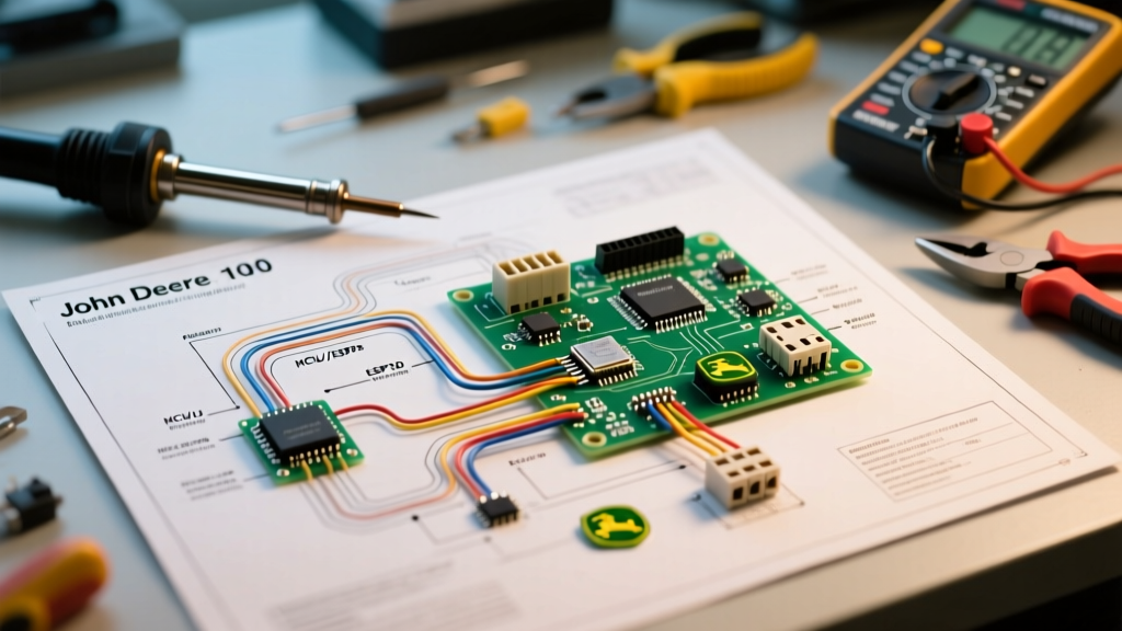
For decades, maintenance technicians relied on static, printed schematics folded into the pockets of their FR (flame-resistant) clothing. While a printed PDF is sufficient for basic continuity checks, it becomes a severe bottleneck when troubleshooting complex, multi-page industrial control panels. In 2026, the modern standard for fault isolation requires a dynamic electrical wiring diagram program that treats schematics not as flat images, but as relational databases of electrical potentials, component cross-references, and terminal strip topologies.
When a 480V centrifugal pump motor fails to start, the issue rarely lies in a single component. It could be a failed interposing relay, a miswired terminal block, or an open neutral in the control transformer secondary. By utilizing advanced diagramming software, engineers and senior technicians can simulate relay logic, track potential paths, and instantly cross-reference wire numbers against the physical Bill of Materials (BOM) before ever opening the panel door.
Top Software Solutions for Electrical Fault Isolation
Not all CAD tools are built for electrical troubleshooting. Mechanical CAD (MCAD) tools lack the underlying electrical intelligence required to understand that a wire connecting Pin 13 to Pin 14 carries a specific voltage potential. Below is a comparison of the leading electrical wiring diagram programs utilized by panel builders and maintenance teams in 2026.
| Software Platform | 2026 Pricing Model | Core Troubleshooting Superpower | Best Use Case |
|---|---|---|---|
| EPLAN Electric P8 | ~$4,500/yr (Subscription) | Potential Tracking & Macro Variables | Complex industrial automation & PLC panels |
| AutoCAD Electrical 2026 | ~$365/mo or $2,945/yr | AI-Assisted Wire Numbering & Signal References | General manufacturing & HVAC control systems |
| ProfiCAD | ~$500 (Perpetual License) | Lightweight netlist generation & fast BOM exports | Independent contractors & residential/light commercial |
| SolidWorks Electrical | ~$6,000+ (Perpetual/Maintenance) | 3D-to-2D wire routing & harness length calculation | Skid-mounted equipment & mobile machinery |
Real-World Troubleshooting: Tracing a 480V Motor Control Fault
To understand the true value of a relational electrical wiring diagram program, let us walk through a real-world troubleshooting scenario. Imagine a NEMA Size 2, 480VAC, 3-phase induction motor driving a pump. The PLC output commands the motor to run, but the main contactor (e.g., an Allen-Bradley 100-C09) does not pull in.
Step 1: Validate the Control Transformer Secondary
Instead of blindly probing with a multimeter, the technician opens the schematic in EPLAN or AutoCAD Electrical. The software's Potential Tracker feature highlights the entire 120VAC control circuit derived from the 480V/120V step-down transformer. The software instantly flags that the control circuit relies on Fuse F2 (Secondary, 2A). The technician verifies F2 first, saving 15 minutes of tracing wires through ducting.
Step 2: Cross-Reference the Interposing Relay
The PLC output is 24VDC, but the contactor coil is 120VAC. The schematic shows an interposing relay (Allen-Bradley 700-HA32Z24) bridging the two voltages. Using the software's cross-reference function, the technician clicks on the relay coil symbol on page 4. The program instantly generates a popup showing the exact physical location: Panel A, DIN Rail 3, Phoenix Contact CLIPLINE terminal block X4:14 and X4:15. The technician goes directly to X4:14, measures 24VDC, and confirms the coil is energized.
Step 3: Terminal Strip Topology and Wire Routing
The relay contacts (Pins 9 and 11) should pass the 120VAC to the contactor coil (A1). However, the software's terminal strip diagram reveals that the wire leaving Pin 11 routes through a remote junction box (JB-04) before reaching the motor starter. The technician checks JB-04 and discovers a loose Wago lever-nut connection caused by high-vibration from the pump. The relational database in the software mapped the physical routing path that a static PDF would have entirely hidden.
Expert Insight: Never rely solely on the schematic line diagram for physical troubleshooting. Always generate and print the Terminal Strip Diagram and 3D Wire Routing Layout from your electrical wiring diagram program. Line diagrams show logical flow; terminal diagrams show physical reality.
Edge Cases and Failure Modes Caught by Dynamic Software
Static drawings are prone to human error during revisions. A modern electrical wiring diagram program acts as a compiler, catching logical and physical errors before they manifest as dangerous field failures.
- Backfed Control Circuits: If a technician accidentally wires a 120VAC feedback signal into a 24VDC PLC input card, the card will explode. Advanced software features 'Potential Definition Points' that will flag a hard error if a wire attempts to bridge two incompatible voltage potentials.
- Wire Gauge vs. Breaker Sizing Mismatches: If a schematic specifies a 20A circuit breaker but the BOM and wire definition specify 14 AWG THHN (rated for 15A in certain ambient conditions), the software's design rule check (DRC) will flag a National Electrical Code (NEC) violation before the panel is built.
- Ghost Voltages and Floating Neutrals: When troubleshooting open neutrals in multi-wire branch circuits, dynamic software can trace the shared neutral bar (X0) across all three phases, ensuring that the neutral conductor is sized correctly and not shared across different GFCI/AFCI protected zones.
Compliance and Industry Standards
When utilizing an electrical wiring diagram program to troubleshoot or redesign industrial machinery, your schematics must adhere to strict regulatory frameworks. In the United States, industrial control panels must comply with NFPA 79 (Electrical Standard for Industrial Machinery). This standard dictates specific wire color codes (e.g., black for 480VAC, red for 120VAC control, blue for DC control, and yellow for interlock circuits wired from external sources).
Furthermore, OSHA's electrical safety standards require that lockout/tagout (LOTO) procedures be backed by accurate, up-to-date schematics. If a technician uses an outdated PDF that fails to show a backfed solar inverter connection, the result can be fatal. Dynamic software ensures that the 'As-Built' schematic in the cloud matches the physical panel on the floor, updating in real-time as redline markups are approved by the lead engineer.
FAQ: Wiring Diagram Software for Technicians
Can I use a tablet in the field to view these dynamic diagrams?
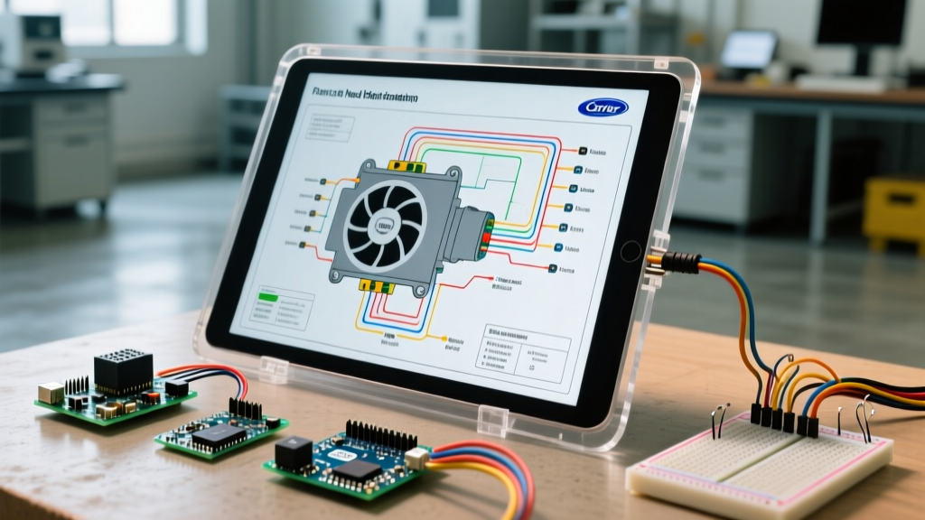
Yes. Most enterprise platforms like EPLAN and AutoCAD Electrical now offer web-based viewers (such as EPLAN eVIEW) that allow field technicians to open the live project database on an iPad or ruggedized tablet. This allows them to click on a component and see its real-time BOM data, replacement part numbers, and cross-references without needing a full CAD license.
Is it worth the cost for a one-man electrical contracting business?
If you are strictly doing residential wiring, a perpetual license for ProfiCAD or even SmartDraw is sufficient. However, if you are building UL508A industrial control panels or troubleshooting VFD (Variable Frequency Drive) harmonics and PLC networks, the subscription cost of AutoCAD Electrical pays for itself by reducing troubleshooting time and preventing catastrophic component miswiring.
How do I handle legacy panels with no existing digital schematics?
The standard procedure in 2026 is to perform a 'point-to-point' ring-out using a tone generator and multimeter, logging the data into a spreadsheet, and then reconstructing the schematic in your chosen electrical wiring diagram program. While tedious, creating a digital twin of a legacy panel is the only way to safely troubleshoot and upgrade it to modern safety standards.