
Introduction to Solar-to-Appliance Circuit Architecture
When off-grid enthusiasts and DIYers search for a reliable wiring diagram for solar panel to appliance setups, they often encounter a dangerous misconception: the idea that you can wire a photovoltaic module directly to a household appliance. In reality, solar panels output fluctuating DC voltage (typically 18V to 42V depending on illumination and temperature), which will instantly destroy the sensitive PCBs and compressor motors of modern appliances. A proper solar appliance circuit requires a buffered architecture utilizing a charge controller, a battery bank, and an inverter.
As of 2026, the democratization of high-efficiency MPPT charge controllers and affordable LiFePO4 (Lithium Iron Phosphate) batteries has made dedicated solar appliance circuits more accessible than ever. Whether you are wiring a 12V DC compressor chest freezer for an off-grid cabin or a 120V AC well pump for a homestead, understanding the exact wire gauges, overcurrent protection devices (OCPD), and busbar topologies is critical for safety and efficiency.
⚠️ CRITICAL SAFETY WARNING: Solar arrays generate lethal DC voltage and high amperage. DC arcs do not self-extinguish like AC arcs. Always install a DC disconnect switch and ensure all panels are covered or disconnected before terminating MC4 connectors. Adhere strictly to NEC Article 690 for solar photovoltaic systems.
Core Components for a 400W Appliance Solar Array
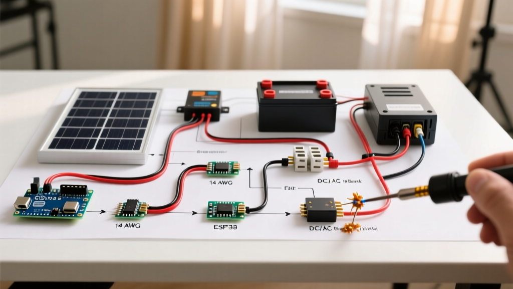
Before tracing the wiring diagram for solar panel circuits, we must define the hardware. The following bill of materials (BOM) represents a robust 400W system designed to run a 120V AC appliance (like a 5,000 BTU window AC unit or a small refrigerator) drawing roughly 400W to 600W of continuous power.
| Component | Recommended 2026 Model | Estimated Cost | Purpose |
|---|---|---|---|
| Solar Panels | 2x 200W Renogy Monocrystalline | $180.00 | Energy harvesting (400W total) |
| Charge Controller | Victron SmartSolar MPPT 100/30 | $185.00 | Regulates PV voltage to battery bank |
| Battery Bank | Power Queen 12V 100Ah LiFePO4 | $239.00 | Energy buffer and stabilization |
| Inverter | Renogy 1000W Pure Sine Wave | $145.00 | Converts 12V DC to 120V AC |
| Busbars & Fuses | Blue Sea Systems 4-Stud + Class T | $65.00 | Central distribution and OCPD |
Phase 1: The DC Side Wiring Diagram (Panels to Battery)
The DC side of your wiring diagram for solar panel systems deals with high voltage, low current (from the panels) and low voltage, high current (from the battery). We will route this through a centralized positive and negative busbar system to avoid 'daisy-chaining' wires directly onto battery terminals, which violates modern electrical codes.
Step 1: Panel to Charge Controller (PV Circuit)
- Combine the Panels: Wire the two 200W panels in series using MC4 connectors to increase voltage (Voc ~45V) while keeping current low (Imp ~10A). This minimizes voltage drop over long wire runs.
- PV Wire Selection: Use 10 AWG UV-rated PV wire for the run from the roof to the charge controller.
- Inline Fusing: Install a 15A inline MC4 fuse on the positive PV wire within 12 inches of the charge controller input.
- Termination: Strip the PV wire and terminate it into the Victron MPPT 'PV' terminals. Torque the terminal screws to 1.2 Nm to prevent thermal runaway at the connection point.
Step 2: Charge Controller to Busbars
Never wire the charge controller directly to the battery. Always route through a busbar with appropriate overcurrent protection.
- Run 8 AWG stranded copper wire from the MPPT 'BAT' positive terminal to the positive busbar.
- Install a 40A ANL fuse between the positive busbar and the battery positive terminal.
- Run 8 AWG wire from the MPPT 'BAT' negative terminal directly to the negative busbar (shunt side).
Phase 2: The Load Side Wiring Diagram (Battery to Appliance)
The load side is where the appliance actually draws power. For 120V AC appliances, this involves the inverter. For 12V DC appliances (like a Dometic fridge), it involves a dedicated DC breaker panel.
Step 3: Battery to Inverter (High Current DC)
This is the most critical high-current connection in your entire system. A 1000W inverter pulling from a 12V battery will draw up to 90 Amps continuously, and potentially 180 Amps during surge (when an appliance compressor starts).
- Wire Gauge: Use 2 AWG pure copper welding cable for the inverter run. Keep this run as short as physically possible (under 5 feet).
- Main OCPD: Install a 150A Class T fuse on the positive cable, mounted within 7 inches of the battery positive terminal. Class T fuses are mandatory here due to their high Amperage Interrupting Capacity (AIC), which safely handles the massive short-circuit currents of LiFePO4 batteries.
- Termination: Crimp 5/16-inch tinned copper ring terminals using a hydraulic crimper. Seal with heat shrink tubing containing adhesive lining to prevent moisture ingress.
Step 4: Inverter to Appliance Receptacle (AC Side)
- Wire the inverter's AC output terminals using 14 AWG THHN stranded wire.
- Route the wires into a standard AC sub-panel or directly to a 15A GFCI breaker.
- From the breaker, run 12/2 or 14/2 Romex (NM-B) to a dedicated 120V 15A receptacle where your appliance will plug in.
- Grounding: Bond the inverter's chassis ground lug to the main system grounding electrode using 6 AWG bare copper wire.
Wire Sizing and Voltage Drop Matrix
Undersized wiring is the leading cause of appliance failure in solar setups. Compressor-based appliances (refrigerators, freezers, AC units) are highly sensitive to voltage drop. If the voltage at the appliance drops below the manufacturer's threshold, the compressor will stall, overheat, and trigger its internal thermal overload protector.
| Circuit Segment | Max Current | Wire Gauge (Up to 5ft) | Wire Gauge (5ft - 15ft) | Acceptable Voltage Drop |
|---|---|---|---|---|
| Panels to MPPT (Series) | 12A | 12 AWG PV Wire | 10 AWG PV Wire | < 3% |
| MPPT to Busbars | 30A | 8 AWG Stranded | 6 AWG Stranded | < 2% |
| Battery to Inverter | 120A (Surge) | 2 AWG Welding Cable | 1/0 AWG Welding Cable | < 1% |
| Inverter to Appliance | 15A (AC) | 14 AWG THHN | 12 AWG THHN | < 3% |
Common Wiring Failure Modes & Troubleshooting
Even with a perfect wiring diagram for solar panel setups, physical installation errors can cause cascading failures. Here are the most common edge cases encountered in the field:
1. MC4 Thermal Runaway
The Failure: The plastic housing of an MC4 connector melts, causing a short circuit or fire.
The Cause: Using non-ratcheting crimpers or mismatched MC4 brands (e.g., mating a Renogy male with a BougeRV female). The internal contact pin fails to seat fully, creating high electrical resistance.
The Fix: Always use a dedicated MC4 ratcheting crimping tool (like the Knipex 97 51 10) and only mate connectors from the same manufacturer. Perform a pull-test of at least 50 lbs on every crimp.
2. Inverter Low Voltage Disconnect (LVD) Nuisance Tripping
The Failure: The inverter shuts down immediately when the appliance compressor kicks on, even though the battery shows 13.4V.
The Cause: Severe voltage drop across the DC wiring or loose busbar connections. When the compressor draws 80A surge, the poor connection causes the voltage *at the inverter terminals* to momentarily sag below 10.5V, triggering the LVD safety shutoff.
The Fix: Upgrade battery-to-inverter cables to 1/0 AWG, ensure all busbar nuts are torqued to 120 in-lbs, and clean any oxidation off the copper terminals.
3. Modified Sine Wave Motor Burnout
The Failure: The appliance motor runs hot, buzzes loudly, and eventually fails.
The Cause: Using a cheap 'Modified Sine Wave' inverter. The stepped waveform causes harmonic distortion and excess heat in inductive loads like compressor motors and pump windings.
The Fix: Exclusively use Pure Sine Wave inverters (Total Harmonic Distortion < 3%) for any appliance containing a motor, transformer, or sensitive microcontroller.
Code Compliance and Authoritative References
Designing a safe solar appliance circuit requires adherence to national and local electrical codes. The guidelines outlined in this wiring diagram for solar panel configurations are derived from the following authoritative standards:
- National Electrical Code (NEC) Article 690: The NFPA's definitive standard for Solar Photovoltaic Systems, dictating rapid shutdown requirements, DC disconnect placement, and OCPD sizing. Read more via the National Fire Protection Association.
- U.S. Department of Energy (DOE): Provides comprehensive guidelines on residential solar integration, inverter sizing, and battery storage safety protocols. Consult the DOE Homeowner's Guide to Solar for grid-tied and off-grid best practices.
- Penn State Extension - Solar Electric Systems: Offers peer-reviewed, university-backed research on wire sizing, voltage drop calculations, and long-term battery degradation metrics. Review their Solar Electric Systems Basic Information guide for academic validation of DIY sizing formulas.
By strictly following this component architecture, utilizing the correct wire gauges, and respecting the physics of DC voltage drop, you can build a solar appliance circuit that is not only highly efficient but will operate reliably for decades.