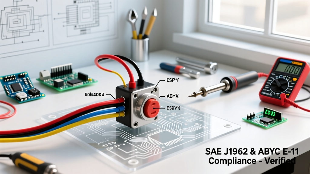

The Hidden Fire Hazards of Aftermarket Ignition Systems
As the trend of classic car restomods, marine repowers, and custom EV conversions accelerates in 2026, the universal ignition switch remains a staple component in custom dashboards and heavy machinery. However, improper installation is a leading cause of electrical fires in custom-built vehicles and marine vessels. A generic wiring diagram found on a forum rarely accounts for voltage drop, inductive kickback, or strict code compliance. To ensure your build passes inspection and operates safely for decades, you must adhere to established standards like SAE J1128 for wire insulation and ABYC E-11 for marine ignition protection.
This guide provides a comprehensive, code-compliant wiring diagram for universal ignition switch applications, focusing on safety interlocks, proper fusing distances, and precise terminal mapping. Whether you are wiring a 12V marine cruiser or a 24V heavy-duty tractor, the principles of safe current routing remain identical.
Decoding the Universal Ignition Switch Terminals
Most universal 4-position or 5-position ignition switches utilize a standardized lettering system on the rear bakelite or plastic housing. Misinterpreting these terminals is the most common cause of melted harnesses and dead batteries. Below is the definitive mapping for standard SAE-compliant switches.
| Terminal | Designation | Function & Load Profile | Recommended Wire Gauge (12V) | Standard Wire Color |
|---|---|---|---|---|
| B | Battery | Main power feed from the battery/solenoid. Handles the cumulative load of all switch positions. | 10 AWG (Primary Feed) | Red |
| I | Ignition | Powers ECU, coil, and dash instruments in 'Run' and 'Start'. Must handle continuous inductive loads. | 12 AWG | Pink / Purple |
| S | Start | Engages the starter solenoid. High momentary current draw (up to 30A+ depending on solenoid). | 10 AWG or 12 AWG | Yellow / Red-Blue |
| ACC | Accessory | Powers radios, wipers, and auxiliary 12V sockets. Active in 'Acc' and 'Run', dead in 'Start'. | 12 AWG or 14 AWG | Brown / Orange |
| ST | Start Relay | Used in older point-ignition systems to provide full 12V to the coil during cranking (bypassing ballast). | 14 AWG | White / Green |
The Code-Compliant Wiring Diagram: Step-by-Step Routing
Follow this precise routing sequence to ensure your wiring diagram for universal ignition switch installations meet both safety and operational benchmarks. This layout assumes a standard 12V negative-ground system with a remote starter solenoid.
Phase 1: Main Battery Feed and Fusing
- Source the Power: Run a 10 AWG XLPE (Cross-Linked Polyethylene) wire from the load side of the main starter solenoid or the main battery distribution bus. Do not connect directly to the raw battery post if a main busbar is present.
- Install the Primary Fuse: According to ABYC E-11 standards and general automotive best practices, the main feed wire to the ignition switch must be protected by a fuse located within 7 inches of the power source. Install a 30A or 40A MIDI/AME fuse holder here. If the 7-inch rule is impossible due to physical constraints, the entire wire run must be encased in split-loom conduit and protected by a 40A breaker at the source.
- Connect to 'B' Terminal: Crimp a high-quality, heat-shrink insulated ring terminal onto the 10 AWG wire and secure it to the 'B' (Battery) terminal on the ignition switch.
Phase 2: Ignition and Accessory Distribution
- Ignition ('I') Routing: Run a 12 AWG wire from the 'I' terminal to the 'Run' side of your ECU, ignition coil, or main relay. Critical Safety Note: If you are using an older points-style ignition with a ballast resistor, you must install a 1N4001 diode in-line to prevent the alternator from backfeeding through the 'I' terminal, which can cause the engine to continue running (dieseling) after the key is turned off.
- Accessory ('ACC') Routing: Run a 12 AWG wire from the 'ACC' terminal to an auxiliary fuse block dedicated to cabin accessories. Never wire high-draw items like cooling fans directly to the ACC terminal; use the switch to trigger a 30A Bosch-style relay instead.
Phase 3: Starter Solenoid Engagement
- Start ('S') Routing: Run a 10 AWG wire from the 'S' terminal to the 'S' or 'Start' trigger post on the remote starter solenoid. Because starter solenoids require a high initial inrush current to pull the heavy copper contacts closed, voltage drop here will result in a 'click-no-crank' scenario. Keep this wire run as short as possible and avoid sharp bends.
- Neutral Safety Switch Integration: For code compliance and operator safety, the 'S' wire must be routed through a neutral safety switch (for automatic transmissions) or a clutch-depress switch (for manuals) before reaching the starter solenoid. This prevents the vehicle from lurching forward if started in gear.
Marine and RV Code Compliance: Ignition Protection
When applying this wiring diagram in marine or RV environments, standard automotive switches are illegal and highly dangerous. Gasoline fumes in bilges or enclosed compartments can be ignited by the internal arcing that naturally occurs when a standard ignition switch breaks a circuit.
Compliance Mandate: Any ignition switch installed in a gasoline-powered marine vessel must be 'Ignition Protected' according to US Coast Guard (USCG) regulations and ABYC E-11 standards. This means the switch is sealed and tested to ensure it will not ignite a surrounding explosive gas mixture. Look for switches explicitly stamped with 'Ignition Protected' or SAE J1171 certification.
For Recreational Vehicles (RVs), the NFPA National Electrical Code (NEC) Article 551 dictates strict separation between 12V DC ignition circuits and 120V AC shore power systems. Ensure your universal ignition switch is mounted in a dedicated 12V DC panel, maintaining at least a 2-inch physical clearance from any AC wiring to prevent inductive interference and catastrophic short-circuit risks.
Real-World Failure Modes & Edge Cases
Even with a perfect diagram, environmental factors and cheap components lead to failures. Here is what our master technicians see in the field:
- Melted Bakelite Housings: Caused by running high-draw accessories (like electric fuel pumps) directly through the 'I' terminal without a relay. The internal copper contacts overheat, melting the switch body and causing a dead short.
- Corrosion-Induced Voltage Drop: Using cheap PVC-insulated wire instead of SAE J1128 XLPE wire. PVC becomes brittle and wicks moisture via capillary action, leading to green corrosion deep inside the crimp joints.
- The 'Run-On' Condition: Failing to install a blocking diode on the 'I' terminal in alternator-equipped classic cars. The alternator's internal diodes can feed 12V back into the ignition circuit, keeping the engine running even with the key removed.
2026 Component Selection & Market Pricing
Selecting the right switch is as critical as the wiring itself. Below is a curated list of heavy-duty, code-compliant universal ignition switches available in the current market, complete with exact part numbers and average 2026 pricing.
| Brand / Manufacturer | Part Number | Application / Rating | Key Features | Avg. Price (USD) |
|---|---|---|---|---|
| Cole Hersee (Littelfuse) | M-750 | Heavy Duty / 36A @ 12V | Steel housing, O-ring sealed, Ignition Protected | $45.00 - $55.00 |
| Sierra Marine | MP41040 | Marine / 15A @ 12V | SAE J1171 Certified, glass-filled nylon, 3-position | $35.00 - $45.00 |
| Pollak | PK38502 | Commercial / 20A @ 12V | Bakelite housing, 4-position, universal fitment | $25.00 - $32.00 |
Note: For comprehensive switch specifications and datasheets, refer to the Littelfuse/Cole Hersee ignition switch catalog.
Post-Installation Testing Protocol
Do not simply turn the key and hope for the best. Follow this multimeter testing protocol to verify the integrity of your wiring diagram for universal ignition switch implementation:
- Continuity Check (Power Off): With the battery disconnected, use a multimeter in continuity mode. Verify that the 'B' to 'ACC' circuit is closed only in the ACC and RUN positions. Verify 'B' to 'S' is closed only in the START position.
- Voltage Drop Test (Cranking): Reconnect the battery. Set your multimeter to DC Volts. Place the red probe on the 'B' terminal and the black probe on the 'S' terminal. Have an assistant crank the engine. The voltage drop across the switch must not exceed 0.5V. A reading higher than 0.5V indicates internal contact resistance or undersized wiring, requiring immediate replacement.
- Parasitic Draw Test: Turn the key to the OFF position and remove it. Connect a multimeter in series (Amps mode) between the negative battery terminal and the ground cable. The draw should drop below 50mA (0.05A) within 10 minutes as modules go to sleep. If draw persists, check for backfeed through the 'I' or 'ACC' terminals.
Frequently Asked Questions (FAQ)
Can I use a universal ignition switch for a 24V heavy-duty truck?
Yes, but you must verify the switch's voltage rating. Many standard universal switches are rated strictly for 12V systems. For 24V military or heavy-duty applications, you must source a switch specifically rated for 24V DC (such as the Cole Hersee 24V series) to prevent internal arcing and contact welding.
Is it safe to solder the wire connections to the ignition switch?
No. The terminals on a universal ignition switch are subjected to mechanical vibration and thermal cycling. Soldered connections can become brittle and crack under vibration, leading to high-resistance joints and fires. Always use high-quality, adhesive-lined heat-shrink crimp terminals (e.g., Ancor or Molex) applied with a ratcheting crimper.
What happens if I swap the 'I' and 'ACC' terminals?
If you swap Ignition and Accessory, your engine will stall the moment you crank the starter, because the 'ACC' terminal cuts power during the 'Start' position to prioritize current for the starter motor. The 'I' terminal remains hot during cranking to keep the ECU and ignition coil alive.