
The 12V DC Motor Reality of Fuel Pumps
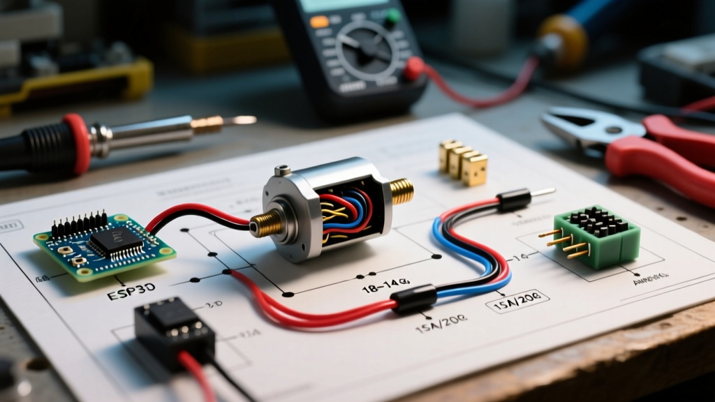
When enthusiasts and technicians approach an electric fuel pump wiring schematic, they often treat the pump as a simple resistive load, akin to a lightbulb. This is a critical engineering fallacy. An electric fuel pump is a 12V DC brushed motor, and like all DC motors, it exhibits complex electrical behaviors—most notably, massive inrush current and inductive kickback. Understanding the electromechanical nature of the pump is the difference between a reliable high-performance fuel system and a stranded vehicle with a melted wiring harness.
At startup, a DC motor has zero rotational speed, meaning it generates zero back-electromotive force (Back-EMF). Without Back-EMF to oppose the supply voltage, the only limitation on current draw is the extremely low resistance of the motor windings. This results in an inrush current that can be 200% to 300% higher than the steady-state running current. Your wiring schematic must be designed to handle this transient spike without blowing fuses or welding relay contacts shut.
Core Components of a Safe Fuel Pump Circuit
A robust motor wiring tutorial for fuel delivery requires more than just connecting a wire to a battery. The circuit must integrate protective devices, switching mechanisms, and high-temperature wiring.
- ISO Mini Relay (Bosch Style): Rated for at least 30A continuous (40A peak). This isolates the high-current motor load from the low-current ignition switch.
- Time-Delay (Slow-Blow) Fuses: Standard fast-acting blade fuses will nuisance-trip during the motor's inrush phase. Time-delay fuses tolerate the brief 2-second startup spike.
- TXL or GXL Wire: Standard PVC-insulated wire melts at lower temperatures. Cross-linked polyethylene (TXL/GXL) is rated for 125°C to 150°C, making it mandatory for engine bay and undercarriage routing near exhaust components.
- Inertia Cutoff Switch: A safety device that physically breaks the relay coil ground or power circuit in the event of a collision, preventing post-crash fuel spray.
The Standard 4-Pin Relay Configuration (DIN 72552)
Automotive relays follow the DIN 72552 terminal numbering standard. Memorizing these pinouts is essential for reading any electric fuel pump wiring schematic:
- Pin 30: Common / Line Input (Direct from battery via main fuse).
- Pin 87: Normally Open (NO) Output (Direct to fuel pump positive).
- Pin 86: Coil Power (Triggered by ignition switch, ECU, or oil pressure switch).
- Pin 85: Coil Ground (Chassis ground or ECU switched ground).
Electric Fuel Pump Wiring Schematic: Step-by-Step Flow
Follow this precise routing sequence to minimize voltage drop and ensure motor longevity.
- Battery to Fuse: Run a primary power wire from the positive battery terminal to a weatherpack fuse holder. Mount the fuse within 18 inches of the battery terminal to protect the entire harness length.
- Fuse to Relay (Pin 30): Route the fused 12V+ line to Pin 30 of the ISO relay.
- Relay to Pump (Pin 87): Run the load wire from Pin 87 through the firewall or undercarriage grommets directly to the positive terminal of the fuel pump hanger or bulkhead connector.
- Ignition to Relay (Pin 86): Tap a 12V+ ignition-on source (or ECU fuel pump trigger signal) through a secondary 5A fuse to Pin 86.
- Grounding (Pin 85 & Pump Negative): Ground Pin 85 to a clean chassis point. Crucially, the fuel pump's negative terminal must have a dedicated, heavy-gauge ground wire returning to the chassis or directly to the battery negative. Never daisy-chain the fuel pump ground with other accessories.
Expert Motor Wiring Insight: When terminating ground connections to the chassis, always sand away paint and powder coating down to bare metal. Apply a layer of anti-oxidant compound (such as No-Ox-Id A-Special) before tightening the ring terminal. This prevents galvanic corrosion, which acts as a hidden resistor and causes severe voltage drop at the motor ground.
Wire Gauge (AWG) and Fuse Sizing Matrix
Selecting the correct wire gauge requires factoring in the specific pump model's running amperage, the physical length of the wire run (positive + negative return length), and the acceptable voltage drop (ideally less than 3%). Below is a reference matrix for popular high-flow aftermarket pumps.
| Pump Model | Running Amps (at 60 PSI) | Peak Inrush Amps | Recommended Fuse (Time-Delay) | Min Wire Gauge (10ft Total Run) | Min Wire Gauge (20ft Total Run) |
|---|---|---|---|---|---|
| Bosch 044 | 12A - 15A | 22A - 25A | 20A Slow-Blow | 12 AWG TXL | 10 AWG TXL |
| Walbro 450 (Hellcat) | 16A - 19A | 28A - 32A | 25A Slow-Blow | 10 AWG TXL | 8 AWG TXL |
| AEM 340lph | 11A - 13A | 18A - 20A | 15A Slow-Blow | 12 AWG TXL | 10 AWG TXL |
| Dual Pump Setup (e.g., 2x Bosch) | 24A - 30A | 45A+ | 40A Slow-Blow (Main) | 8 AWG TXL | 6 AWG TXL |
Advanced Motor Protection: Inertia Switches and Prime Circuits
In modern performance applications, a simple ignition-triggered schematic is insufficient. Engine management systems require a 'prime' cycle to build base fuel pressure before the starter engages, and safety regulations mandate crash-cutoff mechanisms.
Wiring the Prime/Run Dual-Relay Setup
To achieve a 3-second prime cycle followed by continuous run operation, you will utilize two ISO relays and an ECU or dedicated timer module.
- Relay 1 (Prime): Pin 86 is triggered by the ECU's prime output (usually active for 3 seconds when the ignition is turned to 'ON', but before cranking). Pin 87 feeds the pump.
- Relay 2 (Run): Pin 86 is triggered by an oil pressure switch (wired to close at 5-7 PSI) or the ECU's tachometer signal (active once the engine is running). Pin 87 also feeds the pump, wired in parallel with Relay 1's output using a diode to prevent back-feeding.
This configuration ensures the pump runs to prime the rails, shuts off if the engine fails to start (preventing flooded cylinders or fire hazards), and seamlessly hands over to the run circuit once oil pressure is established. For crash safety, wire an FMVSS 301 compliant inertia switch in series with the ground path for both relay coils (Pin 85).
Troubleshooting Common Motor Wiring Failures
When a fuel pump fails prematurely or exhibits low flow, the motor is rarely the culprit; the wiring is usually starving it. Use a digital multimeter to perform a dynamic voltage drop test while the motor is under load.
- Symptom: Pump whines loudly and fuel pressure drops at high RPM.
Diagnosis: Voltage starvation. A brushed DC motor's RPM and torque are directly proportional to supplied voltage. If the pump requires 13.5V but is only receiving 11.2V due to undersized wiring or corroded bulkhead connectors, the motor slows down, flow drops, and the windings overheat. As noted in Fluke's technical guides on voltage drop, testing must be done on the live circuit under load, not with a static continuity test. - Symptom: Fuel pump fuse blows immediately upon key-on.
Diagnosis: You are likely using a standard fast-acting ATO blade fuse instead of a time-delay fuse. The inrush current of a high-flow pump like the Walbro 450 easily exceeds 25A for the first 400 milliseconds. Switch to a slow-blow fuse rated 20% higher than the continuous running amperage. - Symptom: Relay clicks rapidly or gets extremely hot to the touch.
Diagnosis: High resistance in the relay coil ground (Pin 85) or insufficient trigger voltage at Pin 86. If the ECU trigger signal only provides 10V, the electromagnetic coil may not pull the contactor fully closed, causing arcing across Pins 30 and 87. Use a secondary trigger relay if the ECU driver circuit is weak.
Authoritative References & Standards
Proper execution of an electric fuel pump wiring schematic requires adherence to automotive electrical standards. For detailed time-current curves on automotive fuses to properly size your slow-blow protection, consult the Littelfuse Automotive Fuses technical documentation. Additionally, when integrating safety cutoff switches, ensure your implementation aligns with federal motor vehicle safety guidelines regarding fuel system integrity and post-collision shutoff protocols.