
The Role of Capacitors in Panel and Breaker Systems
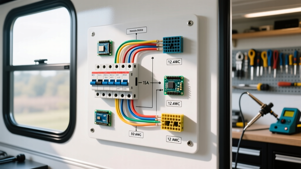
When integrating reactive power components into residential or commercial electrical infrastructure, interpreting a wiring diagram for a capacitor is a foundational skill for any electrical professional or advanced DIYer. Capacitors do not merely store energy; in the context of breaker panels, they serve critical functions ranging from motor-starting torque multiplication in HVAC systems to large-scale Power Factor Correction (PFC) in industrial main distribution boards. As of 2026, with the rise of smart panels and granular energy monitoring, ensuring your capacitor circuits are correctly wired, properly protected by the right breaker size, and compliant with the National Electrical Code (NEC) is more critical than ever to prevent harmonic distortion and catastrophic dielectric failure.
This guide dissects the exact circuit paths, breaker sizing mathematics, and real-world failure modes associated with capacitor panel integration.
Decoding the Wiring Diagram for a Capacitor: Core Circuit Paths
Whether you are wiring a 45/5 µF dual-run capacitor for a residential air handler or a 50 kVAR PFC bank for a commercial panel, the fundamental architecture relies on isolating the capacitor via a dedicated overcurrent protection device (OCPD) and a switching mechanism. Below is the standard current flow for a motor-start/run capacitor circuit originating from a subpanel.
- Line-Side Feed: Power originates from the panel bus bar, passing through a dedicated branch circuit breaker (e.g., a Square D QO 20A or Eaton BR 20A).
- Contactor Integration: The breaker output (load side) routes to the line terminals (L1, L2) of a definite-purpose contactor (such as a Packard C340B 40-amp contactor).
- Control Circuit: The contactor coil (A1, A2) is wired to the 24V control transformer or thermostat circuit, completely isolated from the high-voltage capacitor path.
- Load-Side Distribution: From the contactor's load terminals (T1, T2), the circuit splits. One path feeds the compressor or motor windings (Common, Start, Run).
- Capacitor Parallel Connection: The capacitor is wired in parallel with the motor's start or run windings. The 'C' (Common) terminal of the capacitor connects to the main line feed, while the 'HERM' (Hermetic compressor) or 'FAN' terminal connects directly to the motor's start winding.
NEC-Compliant Breaker Sizing for Capacitor Circuits
The most common error when executing a wiring diagram for a capacitor is sizing the branch circuit breaker based solely on the motor's Full Load Amps (FLA), ignoring the capacitor's reactive current contribution. According to NFPA 70 (NEC) Article 460.8(A), the branch-circuit conductors and the overcurrent protection device must be sized at no less than 135% of the rated current of the capacitor.
Furthermore, NEC 460.6 mandates that capacitors must have a discharge resistor capable of reducing the stored voltage to 50 volts or less within one minute for systems operating under 600V. Always verify the presence of internal bleed resistors before terminating wires.
Capacitor kVAR to Breaker Sizing Matrix (480V 3-Phase System)
| Capacitor Rating (kVAR) | Rated Current (Amps) | 135% NEC Multiplier | Min. Standard Breaker Size | Min. Copper Wire Gauge (THHN) |
|---|---|---|---|---|
| 10 kVAR | 12.0 A | 16.2 A | 20 A | #12 AWG |
| 25 kVAR | 30.1 A | 40.6 A | 45 A | #8 AWG |
| 50 kVAR | 60.2 A | 81.2 A | 90 A | #3 AWG |
| 100 kVAR | 120.4 A | 162.5 A | 175 A | #2/0 AWG |
Note: Torque all breaker lugs to manufacturer specifications. For example, a #8 AWG wire on a standard 45A Eaton breaker typically requires 35 in-lbs of torque to prevent thermal arcing at the terminal.
Power Factor Correction (PFC) Capacitor Banks in Main Panels
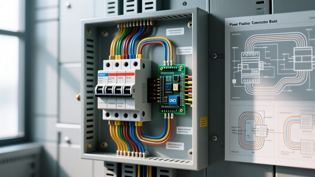
For commercial facilities, integrating a PFC bank directly into the main distribution panel mitigates utility penalty fees caused by inductive loads (like large induction motors and transformers). In 2026, automated PFC controllers, such as the Schneider Electric VarPlus Logic series, dynamically switch capacitor steps in and out of the circuit based on real-time reactive power demand.
When wiring these banks, the main disconnect breaker must be placed upstream of the controller. The current transformer (CT) for the controller must be installed on the main panel feed, upstream of the capacitor bank connection, but downstream of the primary utility meter. If the CT is placed incorrectly, the controller will read the capacitor's own reactive output, leading to a feedback loop that rapidly switches the contactors, destroying them within days.
Real-World Failure Modes and Diagnostic Workflows
Capacitors are consumable components. The dielectric fluid degrades over time due to heat and electrical stress. According to diagnostic guidelines from Fluke's electrical testing resources, visual inspection is only the first step. A bulged CBB65 HVAC capacitor is an obvious failure, but micro-tears in the internal film can cause microfarad (µF) drift without visible deformation.
Step-by-Step Multimeter Diagnostics
- Isolate and Discharge: Turn off the breaker and pull the disconnect. Use a 20k-ohm, 5-watt bleeder resistor across the terminals for 15 seconds. Never short the terminals with a screwdriver; the instantaneous current spike can weld the internal foil layers.
- Capacitance Testing: Set your multimeter (e.g., Fluke 87V or 117) to the Capacitance mode. Connect the leads to C and HERM. A 45 µF capacitor should read within ±6% of its rating (42.3 µF to 47.7 µF). A reading of 38 µF indicates dielectric breakdown; replace it immediately.
- ESR Measurement: For large PFC bank capacitors, use an ESR (Equivalent Series Resistance) meter. An ESR reading above 0.5 ohms in a heavy-duty run capacitor indicates internal drying and impending failure, even if the capacitance value appears normal.
CRITICAL SAFETY WARNING: According to OSHA electrical safety standards, stored electrical energy in high-voltage capacitor banks poses a severe arc flash and electrocution hazard. Always verify zero energy state with a Category IV rated voltage tester before touching any terminal, regardless of the breaker position. Mechanical contactor failure can keep a circuit live even when the coil is de-energized.
Advanced Troubleshooting: Contactor Welding and Harmonic Resonance
If your breaker panel's capacitor circuit trips intermittently, the issue may not be the capacitor itself. In systems with high harmonic distortion (common in facilities with heavy Variable Frequency Drive usage), capacitors can create a parallel resonance condition. This amplifies harmonic currents, causing the branch breaker to trip on thermal overload despite the RMS current appearing normal on a standard clamp meter. To diagnose this, use a power quality analyzer capable of measuring Total Harmonic Distortion (THD). If THD exceeds 5%, you must install detuning reactors in series with the capacitors to shift the resonant frequency away from the 5th and 7th harmonics.
Additionally, if the definite-purpose contactor hums loudly or the contacts weld shut, check the coil voltage. A 24V coil receiving only 19V due to a long, undersized control wire run will fail to pull the armature in completely, causing the contacts to arc and eventually fuse together.
Frequently Asked Questions (FAQ)
Can I wire two run capacitors in parallel to increase the µF rating?
Yes, wiring two capacitors in parallel adds their microfarad ratings together (e.g., two 20 µF capacitors yield 40 µF), while the voltage rating remains the same. However, this is generally discouraged in modern HVAC panels due to space constraints and the increased risk of a single point of failure. It is always better to source the correct single-unit CBB65 capacitor.
Does the polarity matter when wiring an AC run capacitor?
No. Standard AC motor run and start capacitors (like the Dayton or Genteq models) are non-polarized. You can wire the line and load to either terminal of a single capacitor section. However, dual-run capacitors have specific 'C', 'HERM', and 'FAN' terminals that must be strictly followed according to the schematic.
Why does my capacitor breaker trip instantly upon energizing?
An instantaneous magnetic trip indicates a dead short. This is usually caused by a welded contactor, a completely shorted internal capacitor film, or a miswired circuit where the line voltage is being fed directly to ground. Check the contactor contacts for continuity with the power off before replacing the capacitor.