
Marine electrical systems operate in one of the most unforgiving environments on earth. Between constant vibration, high humidity, saltwater corrosion, and the dynamic movement of the hull, a boat's electrical network requires meticulous engineering. When you sit down with boat electrical wiring diagrams, you are not merely tracing lines on a page; you are drafting a survival guide for your vessel's nervous system. A poorly planned installation can lead to catastrophic failures, from autopilot brownouts in heavy weather to devastating electrical fires.
This installation planning guide bridges the gap between theoretical schematics and physical execution. We will dissect how to read, plan, and implement marine wiring diagrams while strictly adhering to modern safety standards and 2026 component realities.
Decoding ABYC E-11 Compliance in Your Schematics
Before drawing a single wire on your diagram, you must understand the governing standard: ABYC E-11 (AC and DC Electrical Systems on Boats). The American Boat and Yacht Council dictates the baseline for marine electrical safety, and your wiring diagrams must reflect these rules natively.
- The 7-Inch Rule: Your diagram must show overcurrent protection (fuses or circuit breakers) placed within 7 inches of the power source. If the wire is enclosed in a continuous conduit or sheath, this distance can be extended to 72 inches, but the schematic must explicitly note this enclosure.
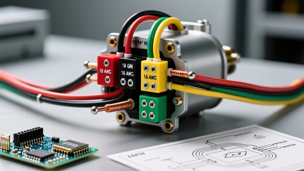
- Conductor Identification: ABYC mandates specific color codes. Your diagrams must label DC positive as red (or yellow for some European imports), DC negative as black or yellow, and AC hot/neutral/ground as black/white/green respectively.
- Ignition Protection: If your diagram routes wiring through engine compartments or enclosed fuel tank areas, every component symbol in that zone must be tagged with an 'IP' (Ignition Protected) rating.
The 4-Phase Installation Planning Workflow
Translating boat electrical wiring diagrams into a physical installation requires a phased approach. Skipping a phase is the primary cause of mid-season electrical gremlins.
Phase 1: The Comprehensive Load Audit
Do not rely on manufacturer nameplate ratings alone. Create a spreadsheet listing every DC and AC load. Calculate the continuous draw versus the intermittent surge draw. For example, a marine windlass might pull 40A continuously but spike to 250A during startup. Your wiring diagram must account for the continuous load for wire sizing, but the surge load for breaker trip-curve selection.
Phase 2: Source Mapping and Bus Bar Topography
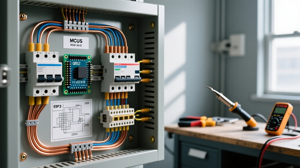
Modern marine diagrams utilize centralized bus bars rather than daisy-chaining. Plan your positive and negative bus bar locations (typically Blue Sea Systems 250A or 600A rated bars) to minimize total wire run lengths. Map out the exact physical path from the battery bank to the main DC breaker panel, ensuring the diagram reflects the actual hull geometry, not just a straight line.
Phase 3: Routing Constraints and Separation
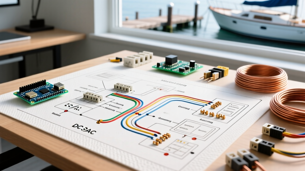
Pro-Tip for Diagram Annotation: Always use distinct line styles on your schematics to differentiate AC and DC routing. If AC and DC wires must run in the same bundle, ABYC requires them to be separated by a physical barrier or at least 2 inches of space to prevent electromagnetic interference (EMI) that can scramble NMEA 2000 networks and VHF radios.
Phase 4: Protection Schematics
Map every single overcurrent device. Note the exact amperage and type (e.g., ANL for high-amperage battery banks, MRBF for terminal mounting, ST Blade for branch circuits).
Marine Wire Sizing and Voltage Drop Matrix
The most critical mistake in marine planning is sizing wire solely for ampacity (heat dissipation) while ignoring voltage drop. In a 12V DC system, a 3% voltage drop is the maximum allowable for critical navigation and communication electronics, while 10% is the limit for non-critical lighting.
The matrix below outlines 12V DC wire sizing based on a 3% voltage drop limit, factoring in the total round-trip circuit length (positive + negative wire). These figures assume premium tinned copper marine wire operating in engine space (higher ambient temperature derating).
| Wire Gauge (AWG) | Max Ampacity (Engine Space) | Max Length for 10A Load (3% Drop) | Max Length for 20A Load (3% Drop) | Max Length for 50A Load (3% Drop) |
|---|---|---|---|---|
| 10 AWG | 21A | 16 ft | 8 ft | N/A |
| 8 AWG | 29A | 26 ft | 13 ft | N/A |
| 6 AWG | 41A | 41 ft | 20 ft | 8 ft |
| 4 AWG | 56A | 65 ft | 32 ft | 13 ft |
| 2 AWG | 78A | 104 ft | 52 ft | 21 ft |
| 1/0 AWG | 150A | 262 ft | 131 ft | 52 ft |
Component Selection and 2026 Pricing Realities
When finalizing your boat electrical wiring diagrams, you must specify exact component models to ensure physical fitment and accurate budgeting. As of 2026, marine-grade components carry a premium, but substituting automotive parts is a guaranteed path to galvanic corrosion.
- Main Distribution Panels: The Blue Sea Systems ST Blade Fuse Block (Model 5025, 6-circuit) remains the industry standard for branch circuits, retailing around $28. For high-density setups, the 12-circuit Model 5035 ($42) includes a negative bus bar, saving installation time.
- Battery Monitoring: Integrate a Victron Energy SmartShunt 500A/50mV ($135) directly into the negative bus bar return path on your diagram. This provides Bluetooth telemetry to your phone without needing a physical panel mount.
- Conductors: Ancor Marine Grade tinned copper wire is the benchmark. Expect to pay approximately $45 for a 100-foot spool of 10 AWG, and upwards of $110 for 4 AWG. The tinning prevents the 'black wire' corrosion syndrome common in untinned copper.
Physical Routing Constraints and Edge Cases
A diagram is only as good as its physical translation. When planning your wire runs, account for these common marine edge cases that rarely appear on standard schematics:
The Bilge Routing Hazard
Never route wiring through the lowest point of the bilge. If the bilge pump fails and water rises, submerged connections will short out or corrode rapidly. Your diagram should explicitly route all wires above the highest conceivable waterline, utilizing the upper hull stringers or deck headliners.
Chafe Points and Bulkhead Pass-Throughs
Fiberglass bulkheads act like saw blades against vibrating wire looms. Every pass-through on your diagram must include a note for a rubber grommet or a 3D-printed TPU cable gland. For sharp metal edges, use split nylon loom secured with UV-resistant zip ties, never standard hardware store ties which become brittle and shatter within one season of UV exposure.
Electromagnetic Interference (EMI) Zones
Keep DC wiring for sensitive instruments (compasses, GPS antennas, sonar transducers) at least 12 inches away from high-current DC cables (inverters, windlasses, bow thrusters) and all AC wiring. If a crossing is unavoidable, your diagram must dictate a strict 90-degree perpendicular intersection to minimize inductive coupling.
Execution: Translating Diagrams to Physical Connections
According to data from the U.S. Coast Guard Boating Safety Division, electrical faults are a leading cause of marine fires. The execution phase is where diagrams meet reality, and poor termination techniques invalidate the best plans.
Abandon the use of standard automotive crimpers and open-barrel terminals. Marine environments demand ratcheting crimping tools (such as the Knoweasy or Titan ratcheting crimpers, ~$35) that ensure a uniform, gas-tight compression every time. Furthermore, every termination must utilize adhesive-lined, dual-wall polyolefin heat shrink (e.g., 3M MFP series). When heated, the inner adhesive melts and seals the wire strands, completely blocking capillary action and moisture ingress.
Finally, implement a strict torque protocol. Loose connections create high resistance, generating heat. Use a calibrated inch-pound torque screwdriver for all bus bar and breaker terminal screws, adhering strictly to the manufacturer's specifications listed on your installation diagram.
Finalizing the As-Built Schematic
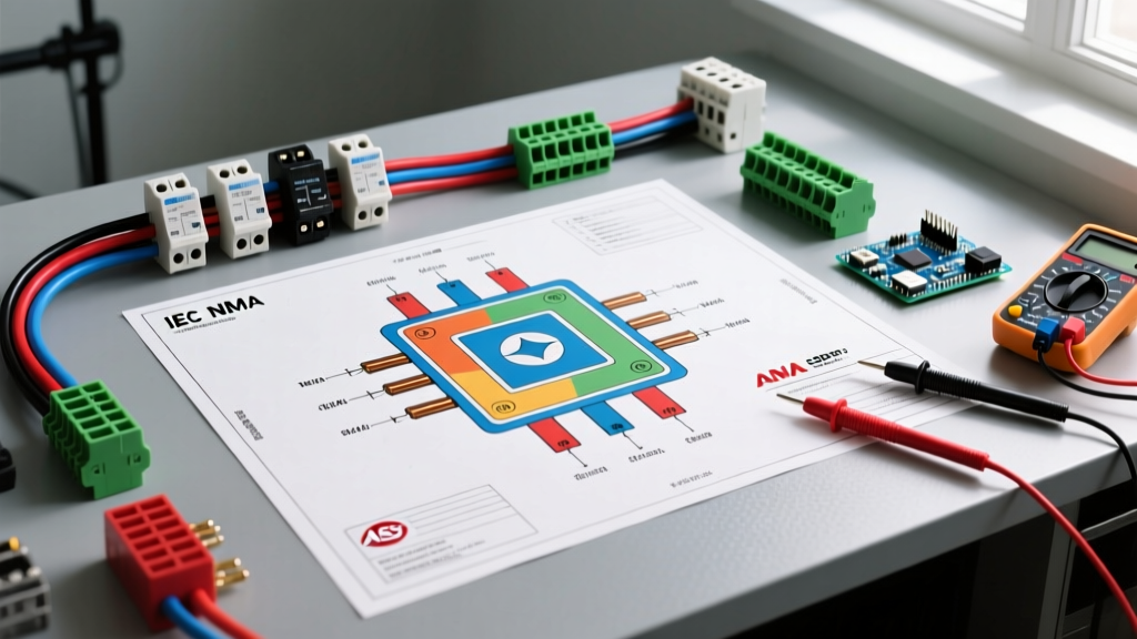
The planning process does not end when the last wire is crimped. As you install, you will inevitably encounter physical obstacles that force minor deviations from the original boat electrical wiring diagrams. Maintain a red pen on hand to mark up the physical printout during installation. Once the vessel is commissioned, digitize these red-line changes to create an accurate 'As-Built' schematic. Laminate this final document and store it in the vessel's physical manual binder, and keep a digital PDF on your marine tablet. When troubleshooting a dead windlass or a flickering nav light at 2 AM, that accurate diagram will be your most valuable tool on the water.