
Introduction to Ford F-150 Trailer Wiring Architecture
When towing with a modern truck, understanding the exact wiring diagram for a Ford F-150 trailer harness is critical for safety and functionality. Whether you are working on a 13th-generation (2015-2020) or the current 14th-generation (2021-2026) F-150, the electrical architecture has evolved significantly from simple hardwired circuits to complex, module-controlled networks. Modern F-150s utilize a dedicated Trailer Module (TRM) that communicates via the CAN-bus system, monitoring current draw and protecting the truck's lighting circuits from short circuits and overloads.
Because of this integration, guessing wire colors or using outdated bypass methods can trigger diagnostic trouble codes (DTCs) or permanently damage the TRM. This comprehensive, step-by-step walkthrough will guide you through reading the OEM wiring diagram, selecting the correct wire gauges, and executing a flawless 7-pin RV blade installation using industry-best practices.
Decoding the Wiring Diagram for a Ford F-150
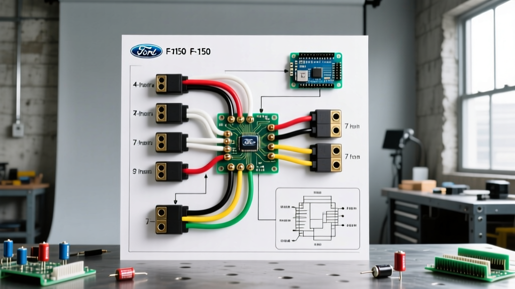
Before cutting or stripping a single wire, you must understand the standard 7-way RV blade pinout and how it maps to the Ford OEM blunt-cut wires typically located under the rear bumper crossmember. The SAE International J286 Standard dictates the physical pin layout, while Ford's specific color coding is detailed in the Ford Truck Body Builder Advisory Service (BBLB) documentation.
7-Way RV Blade Pinout and Ford OEM Wire Mapping
| Pin / Clock Position | Function | Standard RV Wire Color | Ford OEM Blunt-Cut Color | Recommended Gauge |
|---|---|---|---|---|
| 1 (7 o'clock) | Ground | White | White / Black Stripe | 10 AWG |
| 2 (5 o'clock) | Tail / Running Lights | Brown | Brown | 14 AWG |
| 3 (9 o'clock) | Left Turn / Stop | Yellow | Yellow / Light Green | 14 AWG |
| 4 (1 o'clock) | 12V Auxiliary Power | Black (or Red) | Orange / Light Green | 10 AWG |
| 5 (3 o'clock) | Right Turn / Stop | Green | Dark Green / Orange | 14 AWG |
| 6 (11 o'clock) | Electric Trailer Brakes | Blue | Dark Blue | 12 AWG |
| 7 (Center) | Reverse / Backup Lamps | Purple | Purple / White | 14 AWG |
Note: Always verify wire functions with a high-impedance digital multimeter. Ford occasionally updates harness supplier color schemes between model years.
Required Tools and Materials for a Professional Install
Avoid the temptation to use cheap T-tap connectors or standard electrical tape. For a reliable, weatherproof connection that withstands highway speeds and winter road salt, invest in the following specific tools:
- Multimeter: Fluke 117 or equivalent True-RMS high-impedance meter. (Never use a standard 12V incandescent test light on a 2021+ F-150; the low resistance can fry the TRM outputs).
- Wire Strippers: Knipex 12 62 180 for clean, nick-free stripping on 10 to 16 AWG stranded wire.
- Crimpers: Titan 11240 or Knoweasy precision crimping tool for closed-barrel terminals.
- Connectors: 3M Highland or Molex nylon insulated butt splices (12-10 AWG and 16-14 AWG assortments).
- Heat Shrink: 3M adhesive-lined dual-wall heat shrink tubing (shrinks at 221°F / 105°C, seals at 176°F / 80°C).
- Looming: Split loom tubing (1/4 inch and 3/8 inch) and UV-resistant nylon zip ties.
Step-by-Step Walkthrough: Installing the 7-Pin Harness
Step 1: Safety Prep and Locating the OEM Pigtail
Disconnect the negative terminal of the F-150's battery using a 10mm socket to prevent accidental shorting against the chassis. Crawl under the rear bumper and locate the OEM trailer wiring pigtail. On most 2015-2026 F-150s equipped with the factory tow package, this is a blunt-cut bundle wrapped in black corrugated loom, zip-tied to the frame rail just forward of the spare tire or near the rear hitch crossmember. If your truck is a 'tow-prep' model, you may need to purchase the Ford OEM adapter pigtail (Motorcraft part # WPT-1243 or equivalent based on your exact VIN) from the dealer.
Step 2: Routing and Dry-Fitting the Harness
Route your new 7-pin socket harness from the hitch receiver up to the OEM blunt-cut wires. Maintain a minimum clearance of 6 inches from the exhaust system to prevent the heat from melting the wire insulation over time. Use split loom tubing to protect the wires where they pass through metal frame holes or near sharp edges. Do not cut the wires to length yet; leave at least 4 inches of slack on both sides of the splice point for future servicing.
Step 3: Precision Stripping and Crimping
Strip exactly 5/16 inch of insulation from both the Ford OEM wire and the aftermarket harness wire. Slide a piece of adhesive-lined heat shrink tubing onto one side of the wire pair before crimping. Insert the wires into the appropriately sized nylon butt splice (red for 14-16 AWG, blue for 12 AWG, yellow for 10 AWG). Crimp using the correct die on your tool, ensuring the crimp indent is centered on the barrel and the wire strands are flush with the end of the metal barrel without protruding.
Step 4: Heat Shrinking and Weatherproofing
Slide the adhesive-lined heat shrink over the crimped barrel. Using a heat gun set to medium (avoid open flames like lighters, which cause uneven shrinkage and soot buildup), apply heat evenly starting from the center and moving outward. Stop heating the moment you see a small bead of clear adhesive melt out from both ends of the tubing. This indicates a complete, watertight seal that will prevent galvanic corrosion between copper strands.
Step 5: Securing and Reconnecting
Secure the newly spliced harness to the frame rail using UV-resistant zip ties placed every 10 to 12 inches. Ensure the harness is not pulled taut when the rear suspension articulates over bumps. Reconnect the negative battery terminal. Turn on the F-150's running lights and use your multimeter to verify 12.2V to 12.6V at Pin 2 of the 7-way socket.
Common Failure Modes and Advanced Troubleshooting
Even with a perfect physical installation, modern F-150s can present unique electrical gremlins if the TRM detects anomalies. Here is how to diagnose the most common post-installation issues:
1. Trailer Brakes Lock Up When Headlights Are Turned On
The Cause: This is the classic symptom of crossed wires between the Tail/Running light circuit (Brown, Pin 2) and the Electric Brake circuit (Blue, Pin 6). Because the running lights draw continuous current, that 12V feed is mistakenly sent to the trailer's brake magnets.
The Fix: Re-verify your pinout at the socket using a multimeter. Ensure the blue wire is strictly mapped to the 11 o'clock position and the brown wire to the 5 o'clock position.
2. TRM Fault Codes and 'Trailer Wiring Fault' Dashboard Message
The Cause: The 14th-gen F-150 TRM actively monitors circuit resistance. If you used undersized wire (e.g., 16 AWG instead of 10 AWG for the 12V Aux or Ground circuits), the voltage drop under load will exceed the TRM's threshold, causing it to shut down the circuit and throw a DTC like B2A25 (Left Turn Signal Circuit Open) or B2A30 (Trailer Running Lamp Circuit Fault).
The Fix: Check voltage drop across the ground and power circuits under load. A healthy circuit should show less than 0.5V drop. If it exceeds this, upgrade the wire gauge or clean the chassis ground point using a wire wheel and dielectric grease.
3. Intermittent Flickering of Trailer LED Lights
The Cause: LED trailer lights draw significantly less current than incandescent bulbs. The Ford TRM may interpret this low current draw as a 'burnt out bulb' and pulse the circuit to check for continuity, resulting in a strobe effect.
The Fix: Install inline LED load resistors (typically 50W, 6-ohm) on the turn signal circuits, or use a TRM-compatible PWM adapter module designed specifically for low-draw LED trailers.
Expert Tip: Never pierce the insulation of modern Ford OEM wiring with 'vampire' taps to test for power. Piercing the jacket allows moisture to wick into the stranded copper via capillary action, leading to green corrosion (copper oxide) that will break the wire internally months down the road. Always back-probe connectors or test at the blunt-cut ends.
Frequently Asked Questions
Do I need to flash the F-150's PCM after installing a 7-pin harness?
If your truck came with the factory Class IV hitch and 4-pin connector, upgrading to a 7-pin usually only requires splicing the additional wires (Blue for brakes, Black/Red for 12V aux, Purple for reverse) and installing a dash-mounted brake controller. However, if your truck did not have a factory tow package, you will likely need a dealership or tuner to enable the Trailer Brake Controller module in the BCM/PCM via FORScan or an OBD-II flash.
Can I use a 4-pin to 7-pin adapter instead of hardwiring?
Yes, but with severe limitations. A simple plug-in adapter will give you tail lights, brake lights, and turn signals. It will not provide the 12V auxiliary power needed to charge a trailer battery, nor will it provide the dedicated blue wire circuit required for an electronic brake controller. For any trailer weighing over 3,000 lbs with electric brakes, a hardwired 7-pin diagram execution is mandatory.
For further reading on OEM towing specifications and upfitter guidelines, always consult the Ford Truck Body Builder Layout Books and reference the etrailer.com Wiring FAQ for vehicle-specific adapter part numbers and visual guides.