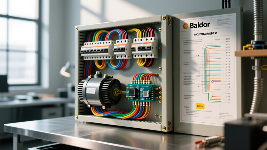

Decoding the Baldor Nameplate and Internal Diagram
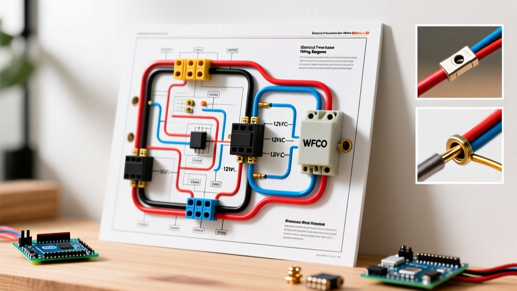
Before pulling a single wire through conduit, the foundation of any successful installation lies in correctly interpreting the Baldor electric motor wiring diagram printed on the nameplate. As we navigate the 2026 landscape of industrial automation, ABB’s Baldor-Reliance line—particularly their IE4 and IE5 premium efficiency models—features denser terminal boxes and more complex internal thermal protection schemes than legacy models.
When you open the peckerhead (connection box) of a standard 9-lead, three-phase Baldor motor (such as the popular M3558T or EM3770T), you will find a diagram dictating High Voltage (460V) and Low Voltage (230V) configurations.
- High Voltage (Wye/Star): Leads 4, 5, and 6 are tied together and insulated. Power is applied to leads 1, 2, and 3. This configuration puts the internal coils in series, dividing the voltage across two windings per phase.
- Low Voltage (Delta/Parallel): Leads 1 & 7, 2 & 8, and 3 & 9 are tied together, with power applied to these three junctions. This places the coils in parallel, requiring double the current but operating at half the voltage.
Expert Warning: Never rely solely on the physical position of the wires from the factory. Always verify the motor's voltage rating against your panel's bus voltage. Wiring a 230V-configured Baldor motor to a 480V panel will result in immediate, catastrophic insulation failure and a violent arc flash.
The Panel & Breaker Paradigm: NEC Article 430
The most critical mistake intermediate electricians make when integrating a Baldor motor into a distribution panel is applying standard branch circuit rules (NEC Article 210) to motor circuits. Motor circuits are governed exclusively by NFPA 70: National Electrical Code (NEC) Article 430.
Why Standard Branch Circuit Rules Fail Here
For a standard receptacle or lighting circuit, you size the breaker to protect the wire (e.g., 12 AWG wire gets a 20A breaker). If you apply this logic to a Baldor electric motor wiring diagram, the breaker will trip instantly upon startup. Why? Because of Locked Rotor Amps (LRA). A motor draws 600% to 800% of its Full Load Amps (FLA) for a few seconds during startup to overcome inertia.
Under NEC 430.52, the branch-circuit short-circuit and ground-fault protective device (the breaker) is allowed to be sized significantly larger than the wire's standard ampacity to accommodate this inrush current. The running overcurrent protection is handled separately by an overload relay located in the motor starter enclosure, not the panel breaker.
Breaker and Wire Sizing Matrix
The following matrix provides baseline sizing for common Baldor three-phase, TEFC (Totally Enclosed Fan Cooled) motors operating at 460V, 60Hz. Wire sizing is based on 75°C THHN copper conductors in a raceway with an ambient temperature of 30°C (86°F).
| Motor HP | Baldor Model Ref | FLA (460V) | Min Wire Gauge (THHN) | Max Inverse-Time Breaker | Overload Relay Setting |
|---|---|---|---|---|---|
| 1.5 HP | M3558T | 2.1A | 14 AWG | 15A | 2.6A (125% FLA) |
| 3 HP | EM3770T | 4.1A | 14 AWG | 15A | 5.1A (125% FLA) |
| 5 HP | EM3585T | 6.8A | 12 AWG | 15A | 8.5A (125% FLA) |
| 10 HP | EM3615T | 13.0A | 10 AWG | 30A | 16.2A (125% FLA) |
| 25 HP | EM4103T | 32.0A | 6 AWG | 70A | 40.0A (125% FLA) |
Note: The 'Max Inverse-Time Breaker' is calculated at 250% of FLA per NEC 430.52, rounded down to the nearest standard breaker size (NEC 240.6). If the motor fails to start due to high-inertia loads, NEC 430.52(C)(1)(Exception No. 1) permits increasing this to 300%, but this requires documented engineering approval.
Configuring the Motor Starter and Overload Relay
The Baldor electric motor wiring diagram extends beyond the peckerhead; it includes the control circuit integration. In 2026, most industrial panels utilize NEMA-rated combination motor starters. Let's look at wiring a standard 10HP Baldor motor using an Eaton NEMA Size 2 starter.
- Line Side Power: Route the 3-phase power from the panel breaker to the top of the contactor (L1, L2, L3).
- Load Side Power: Connect the bottom of the contactor (T1, T2, T3) to the top terminals of the bimetallic overload relay block.
- Motor Feed: Run your 3-phase conductors from the bottom of the overload relay directly to the Baldor motor's peckerhead (Leads 1, 2, and 3 for high voltage).
- Control Circuit (A1/A2): The contactor coil (typically 120VAC) requires a separate control circuit. Wire a 120V hot line through a stop/start push-button station to the A1 terminal. Wire the A2 terminal back to the neutral bus. Ensure you wire a normally-open (NO) auxiliary contact in parallel with the start button to create the standard 'seal-in' (holding) circuit.
Setting the Overload Dial
Modern overload relays, like the Siemens 3RU series or ABB AF contactors, feature adjustable dials. You must set this dial to exactly 115% to 125% of the motor's nameplate FLA, as mandated by NEC 430.32. If the nameplate reads 13.0A, set the dial to 16.2A. This protects the motor from burning up if the mechanical load binds, while allowing the panel breaker to handle short circuits.
2026 Field Failures: Edge Cases and Troubleshooting
Even with a perfect interpretation of the Baldor electric motor wiring diagram, field conditions introduce variables that cause failures. According to the Fluke Motor Troubleshooting Guide, electrical anomalies account for over 40% of premature motor deaths. Here are the specific edge cases to monitor:
1. Single-Phasing (The Silent Killer)
If one pole of your panel breaker fails, or a fuse blows on one phase, the Baldor motor will continue to run on the remaining two phases. It will draw roughly 173% of its normal FLA on those two legs. If your overload relay lacks phase-loss sensitivity, the motor will overheat and the stator windings will melt. Solution: Always specify Class 20 or Class 30 solid-state overload relays with inherent phase-loss and phase-unbalance detection for critical Baldor applications.
2. Voltage Unbalance Exceeding 1%
In large facilities, single-phase loads (like heavy 277V lighting or HVAC units) can unbalance the 3-phase panel bus. A mere 2% voltage unbalance across the three legs feeding your Baldor motor can cause a 20% temperature rise in the windings. Use a True-RMS power quality analyzer at the contactor line-side terminals before energizing the motor. If unbalance exceeds 1%, you must derate the motor or balance the panel loads.
3. VFD Integration and Bearing Fluting
If your wiring diagram is bypassing a traditional panel starter in favor of a Variable Frequency Drive (VFD), you must address common-mode voltages. VFDs output high-frequency PWM pulses that can capacitively couple to the Baldor motor shaft, discharging through the bearings and causing 'fluting' (microscopic pitting). Solution: Install an AEGIS shaft grounding ring on the drive end of the Baldor motor and ensure the VFD cable is a symmetrical, shielded VFD cable (like Belden 295) grounded at both ends.
Expert FAQ on Baldor Motor Panel Wiring
Can I use a standard thermal-magnetic breaker instead of a Motor Circuit Protector (MCP)?
Yes, but they serve different roles. A standard thermal-magnetic breaker (Inverse-Time) is permitted by NEC 430.52 for branch short-circuit protection when paired with a separate overload relay in a motor starter. An MCP (which only has magnetic short-circuit protection and no thermal trip) is typically used in factory-assembled, listed combination motor controllers where the overload and MCP are tested as a single unit. For field-built panels, stick to standard inverse-time breakers.
How do I wire the internal thermostat (T1/T2) on a Baldor motor?
Many premium Baldor motors include embedded PTC thermistors or bimetallic thermostats (usually labeled T1 and T2 on the nameplate). These are not power leads. They are low-current control circuit leads designed to be wired in series with your contactor coil circuit or routed to a dedicated motor protection relay. If the motor exceeds its internal thermal limit (usually 155°C for Class F insulation), the T1-T2 circuit opens, dropping out the contactor and shutting off the motor.
What is the maximum allowable voltage drop for the feeder wire?
While the NEC recommends a maximum 3% voltage drop for branch circuits and 5% overall, motor starting currents (LRA) can cause severe transient voltage dips. If your Baldor motor is located far from the panel, calculate the voltage drop using the LRA, not the FLA. If the voltage at the motor terminals drops below 85% of nominal during startup, the contactor coil may chatter or drop out, causing severe arcing and contactor welding. Upsize your conductors to mitigate this.
For further technical specifications on premium efficiency motor integrations, refer to the ABB IE4 Super Premium Efficiency Motors documentation portal, which houses the master repository for all modern Baldor-Reliance wiring schematics and torque specifications.